Eureka AIR delivers breakthrough ideas for toughest innovation challenges, trusted by R&D personnel around the world.

Polymer supported electrodes

Inactive Publication Date: 2011-07-28
MOLECULAR NANOSYST
View PDF6 Cites 88 Cited by
  • Summary
  • Abstract
  • Description
  • Claims
  • Application Information

AI Technical Summary

Benefits of technology

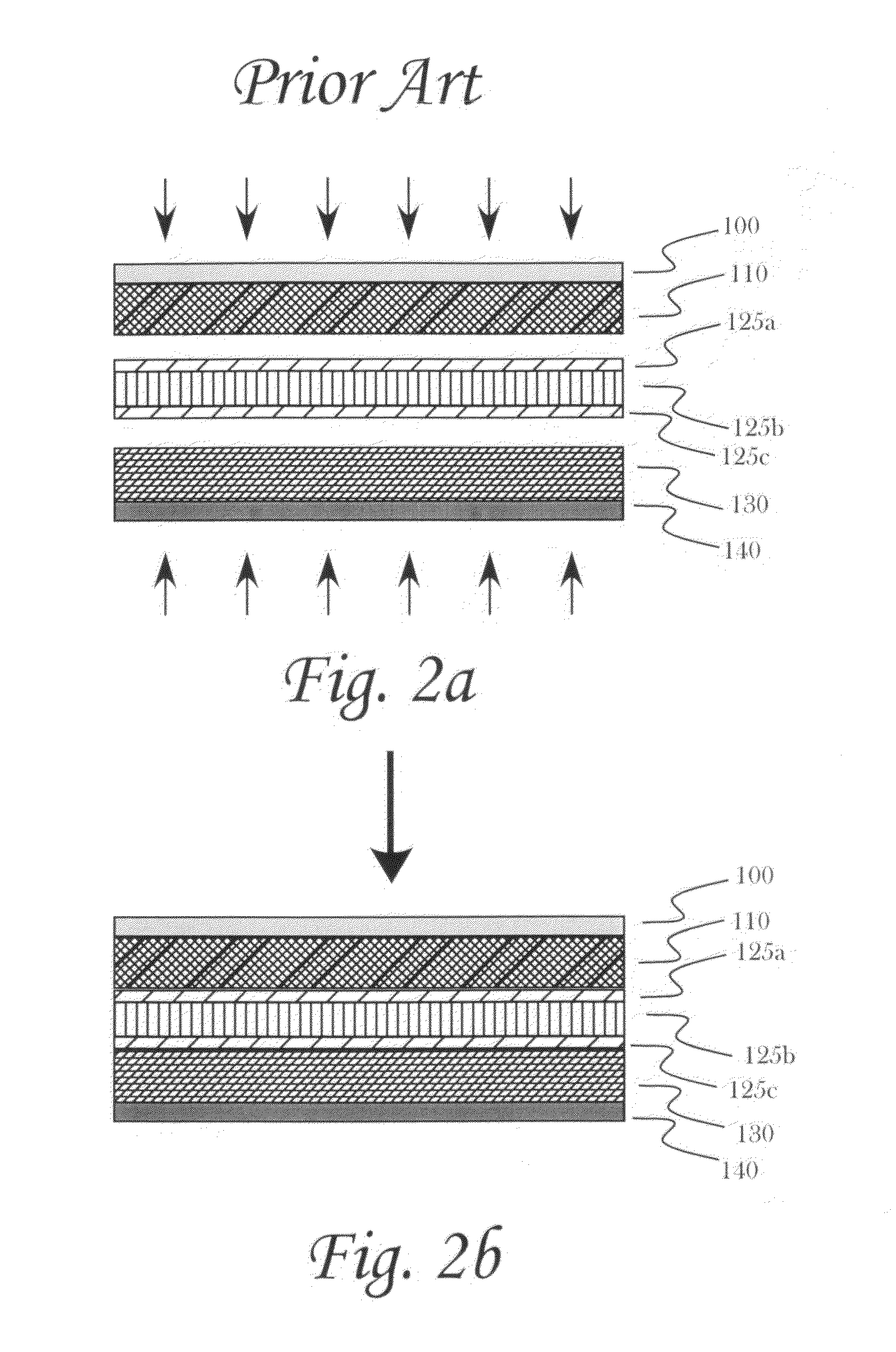
[0014]In some embodiments, the electrode support may act in a way that helps to prevent thermal runaway resulting from dendrite formation within the battery, preferably by having the electrode support comprises two or more layers of polymer sheets with different melting points being laminated to provide the electrode support.
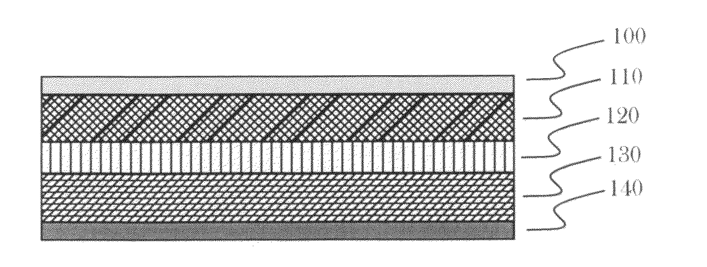
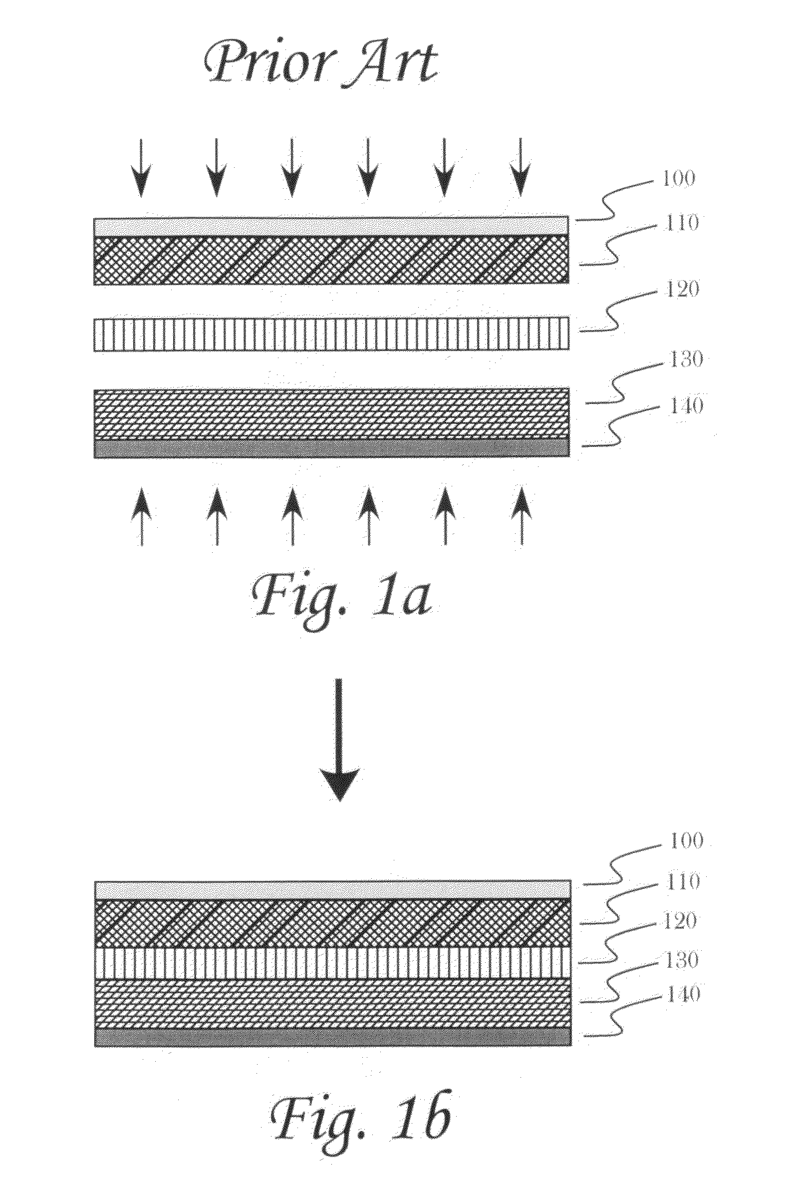
[0023]In one aspect of the invention, the electrode support may act as a battery separator. In some embodiments, the electrode support functions as a battery separator that comprises a polymer sheet having thereupon an electrode material, the polymer sheet being disposed adjacent another electrode, for example, but not limited to, a cathode or an anode, wherein the electrode support with its electrode material and the other electrode are situated within a liquid electrolyte, a gel electrolyte, or a molten salt battery. In preferred embodiments, the separator prevents physical contact between anode and cathode material and may serve as an electrolyte reservoir to provide for ionic transport between the electrodes through the pores of the separator. In some embodiments, the separator may participate in an electrochemical reaction, for example, but not limited to, lithium ion secondary storage processes. In some embodiments, ion permeability and dielectric properties of the separator may be improved to improve energy density, power density, cycle life and safety of the battery, and preferably the separator may be stable against acidic, basic, aqueous, organic, and electrolytic battery environments. The preferred separator may have additives that afford chemical and electrochemical stability, and mechanical strength to prevent dendrite growth. Structural and / or chemical variants may be incorporated into the battery and / or the separator to minimize self-discharge and penetration of metal dendrites formed during charging for a secondary battery. For high energy and power densities, the separator should be very thin, highly porous, and capable of withstanding high temperature incurred by fast discharge.
[0025]In some embodiments, the electrode support may act in a way that helps to prevent thermal runaway resulting from dendrite formation within the battery in that the electrode support comprises two or more layers of polymer sheets with different melting points being laminated to provide the electrode support, when used as a battery separator, with thermal shutdown capability.

Problems solved by technology

In many situations, the thickness of a metal foil is driven more by mechanical issues than electrical requirements.
The additional metal foil thickness adds to the overall weight, volume, and cost of the resulting battery.

Method used


Image

  • Polymer supported electrodes
  • Polymer supported electrodes
  • Polymer supported electrodes

Examples


example 1

Preparation of Support

[0067]The surfaces of two 25 mm by 75 mm porous polyethylene battery separator membranes were exposed to plasma for 10 minutes. A poly-(hydroxymethyl methacrylate) (pHEMA) coating was then applied to the treated separator membrane. Monomeric HEMA was mixed with water at a 5% v / v ratio to which the catalyst FeCl2 was added to yield a final FeCl2 solution molarity of 2.5×10⁻⁴. The treated separator membrane was promptly immersed into the HEMA solution for 3 hours, removed from the solution, rinsed with water, rinsed in ethanol, and allowed to air dry.

example 2

Separator Membrane Mounting

[0068]The plasma treated membrane was placed upon an aluminum foil sheet covering one side of a 25 mm by 75 mm standard microscope slide to form a membrane / foil / glass slide sandwich and was held together with small binder clips to form a membrane-electrode sandwich.

example 3

Preparing Stock Nanotube Solution

[0069]Multi-walled carbon nanotubes (MWCNTs) were readied by suspending 2400 mg of MWCNT in 160 ml of 15.6M H2(NO3) and refluxed for 10 hours using an oil bath at 125° C. and collected and dried by filtration. The average length and diameter of the MWCNTs ranged from 5 to 50 μm and 2-25 nm, respectively. After drying, 60 mg of the acid treated MWCNTs was suspended in 20 ml of 200 proof ethanol in a beaker placed for 45 minutes placed in a 70 watt ultrasonic cleaning water bath operating at 40 kHz to yield a stock MWCNT solution.


PUM


Abstract

Methods and devices arising from the practice thereof for making and using battery electrodes formed onto ion permeable, electrically non-conductive substrates, preferably battery separators are disclosed herein. Electrodes are formed onto substrates using a variety of methods including, but not limited to, spray coating and electrophoretic deposition. Electrically conductive layers may be applied to the electrode coating layer side opposite or adjacent to the substrate to act as current collectors for the battery. Multilayer devices having alternating layers of conductive layers, electrode layers and substrates, wherein the conductive layers may be in electrical communication with other conductive layers to form a battery.

Description

CROSS-REFERENCE TO RELATED APPLICATIONS[0001]This application claim priority under 35 U.S.C. §119(e) to U.S. Provisional Patent Application Ser. No. 61 / 298,893 by Du, et al., filed on Jan. 27, 2010, which is herein incorporated by reference in its entirety for all purposes, and the specific purposes described herein.STATEMENT REGARDING FEDERALLY SPONSORED RESEARCH OR DEVELOPMENT[0002]No part of the invention described herein was the result of Federally sponsored research or development.FIELD OF THE INVENTION[0003]The invention relates to the fields of electrode manufacturing, web coating, energy storage, energy efficiency, batteries, secondary batteries, and lithium ion batteries.BACKGROUND[0004]Rechargeable batteries play an important role in everyday modern life. From portable electronics to hybrid electric and electric vehicles, rechargeable batteries are an indispensable part of our society. The advent of lithium ion batteries was an important development in the field of recharg...

Claims


Application Information

Patent Timeline
IPC IPC(8): H01M4/62B05D5/12B82Y30/00H01M50/414H01M50/42H01M50/426H01M50/451
CPCB82Y30/00Y02E60/122H01M2/166H01M2/1686H01M4/0402H01M4/0419H01M4/131H01M4/133H01M4/1391H01M4/1393H01M4/583H01M4/625H01M10/052H01M10/4235H01M2/1653Y02E60/10H01M50/446H01M50/451H01M50/414H01M50/426H01M50/42
Inventor DU, CHUNSHENGDONG, CLARKPAN, LAWRENCE S.PENG, SHUFU
Owner MOLECULAR NANOSYST
Why Eureka
Eureka Blog
Learn More