Single photon emission system

a single photon and emission system technology, applied in the field of single photon emission system, can solve the problems of reducing limiting the security of conventional optical data transmission systems, and limiting the reliability of single photons, so as to reduce the loss of single photon intensity resulting from single photons emitted towards a side portion of optical fibres

Inactive Publication Date: 2011-07-21
UNIVERSITY OF MELBOURNE
View PDF3 Cites 2 Cited by
  • Summary
  • Abstract
  • Description
  • Claims
  • Application Information

AI Technical Summary

Benefits of technology

[0025]The holder may also be provided in the form of an optical fibre portion that comprises a core region that is surrounded by a region which has an optical bandgap at an energy that corresponds to an energy of the emitted single photons. In this case the particle for generating the single photons typically is positioned within the core region, which may be hollow region, and, because of the optical bandgap, emission of single photons in a direction along the core region is facilitated. Consequently, loss of single photon intensity resulting form single photons emitted towards a side portion of the optical fibre is reduced.

Problems solved by technology

However, conventional optical data transmission systems typically only provide limited security and unauthorised access to information associated with the transmitted data may be a problem.
However, such systems guarantee single photons with a reliability of only 85%.
True sources of single photons are available at present only in laboratories and comprise very large and complicated set-ups.

Method used


Image

  • Single photon emission system
  • Single photon emission system
  • Single photon emission system

Examples


Embodiment Construction

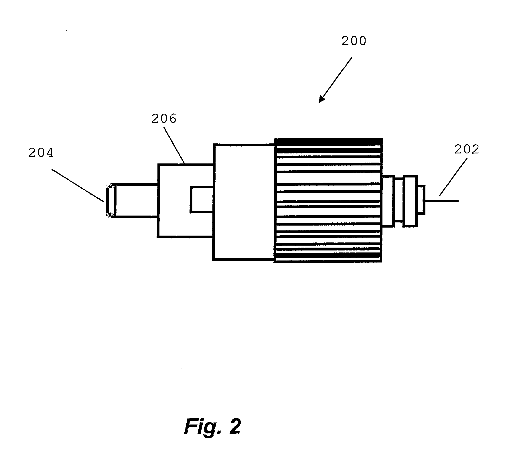
[0038]Referring to FIGS. 1 to 3, a method of forming a single photon emission system and a single photon emission system according to specific embodiments of the present invention are now described.

[0039]FIG. 1 illustrates the method of forming a single photon emission system in accordance with a specific embodiment.

[0040]The method 100 comprises step 102 of identifying single photon emission properties of a particle located at a first location. The particle is arranged for single photon emission at a predetermined wavelength in response to a suitable excitation.

[0041]In this embodiment the particle is a diamond particle and identifying single photon emission also comprises depositing a plurality of the diamond particles on a substrate. The diamond particles may be provided in the form of a diamond powder. The particles of the diamond powder are suspended in a suitable solution, such as methanol, and applied to a substrate. The methanol is then evaporated resulting in the deposition...


PUM


Abstract

The present disclosure provides a method of forming a single photon emission system and a single photon emission system. The method comprises providing a single photon source arranged for single photon emission at a predetermined wavelength in response to a suitable excitation. The single photon source comprises a particle for generating the single photons. The method also comprises providing an optical pump source arranged to provide the suitable excitation in the form of suitable photons. In addition, the method comprises adjusting a pathway of the photons provided by the optical pump source and a position of the single photon source relative to each other so that the single photon source is located at a predetermined location relative to the pathway of the photons provided by the optical pump source and in use single photons are emitted by the single photon source. Providing the single photon source comprises identifying the particle for generating the single photons at a location that is remote from the predetermined location.

Description

FIELD OF THE INVENTION[0001]The present invention broadly relates to a photon emission system.BACKGROUND OF THE INVENTION[0002]Optical fibres provide avenues for transmission of large quantities of data at high speed. However, conventional optical data transmission systems typically only provide limited security and unauthorised access to information associated with the transmitted data may be a problem.[0003]Quantum communication systems are optical data transmission systems that enable secure transmission of the data. Quantum communication relies on the principals of quantum mechanics and requires transmission of single photons in contrast to a large number of photons that are transmitted using conventional optical data transmission systems. If the data is transmitted in the form of pulses of single photons, it can be verified if the data has been accessed and / or changed in any way by an unauthorised party.[0004]Current quantum communication systems rely on attenuated laser light ...

Claims


Application Information

Patent Timeline
Patent Type & Authority Applications(United States)
IPC IPC(8): G21K5/00
CPCH04B10/70
Inventor TRPKOVSKI, STEVENSIMPSON, DAVID ALLANAMPEM-LASSEN, ERICGIBSON, BRANT CAMERON
Owner UNIVERSITY OF MELBOURNE
Why Eureka
Try Eureka