
Apparatus and method for depositing alkali metals

Inactive Publication Date: 2011-07-14
QUANTUMSCAPE CORP
View PDF7 Cites 36 Cited by
  • Summary
  • Abstract
  • Description
  • Claims
  • Application Information

AI Technical Summary

Benefits of technology

[0013]Objects of the present invention include the following: providing a method for making a solid electrolyte having high alkali (preferably lithium) ion conduction; providing a method for making a solid electrolyte by depositing a precursor compound that may be doped with alkali metal and heat treated to create a final electrolyte composition; providing a method for assembling an all solid state lithium battery; providing an improved solid state lithium ion conducting film; and, providing a manufacturing friendly and an improved solid state lithium battery. These and other objects and advantages of the invention will become apparent from consideration of the following specification, read in conjunction with the drawings.
[0014]According to one aspect of the invention, a Li ion conductive electrolyte comprises a compound having the composition LixAlz-yGaySw(PO4)c wher

Problems solved by technology

Safety problems arise mainly from the presence of volatile organic solvents and cathode materials, which undergo exothermic reactions under certain operational and abuse conditions, potentially leading to catastrophic thermal runaway.
The presence of liquids also causes lithium dendrite growth under conditions of uneven current distributions, especially at high rates of charge / discharge.
Finally, traditional Li-ion cell manufacturing is extremely capital-intensive creating substantial financial barriers to scaling manufacturing.
Though thio-LISICON solid state electrolytes of the form LISP, LiSiPS, LiGePS, or in general LixM1-yM′yS4 (M′=Si, Ge, and M′=P, Al, Zn, Ga, Sb) have been found with ionic conductivity comparable to that of liquid electrolyte [see Masahiro et al., Solid State Ionics 170:173-180 (2004)], the method of growth is often expensive and cumbersome, and the resulting electrolyte materials are in pellet, ceramic / glass plate, or powder forms, making their integration in a large format solid state lithium ion battery difficult to implement.
In one case, these are used in expensive vacuum systems to deposit thin films of the electrolyte.
The use of this process to deposit 0.1 to 2 μm film to block lithium dendrite formation on anode in a liquid electrolyte based lithium-ion battery will incur some price penalty; however, its use in depositing a thicker film suitable for a large format all-solid-state lithium ion battery will be uneconomical.
In the other case, the use of ball milling to obtain finer powder appears cumbersome.
The integration of glass ceramic electrolyte, obtained from powder melting at high temperature and quenching, in the overall battery fabrication steps is not trivial and may be impossible.
However, the option where melt quenching is omitted and pelletization of combined anode, electrolyte, and cathode to fabricate the battery is feasible and slightly less expensive.
But one can foresee a bulky battery, perhaps in a coin cell format, with lower energy per unit mass.

Method used


Image

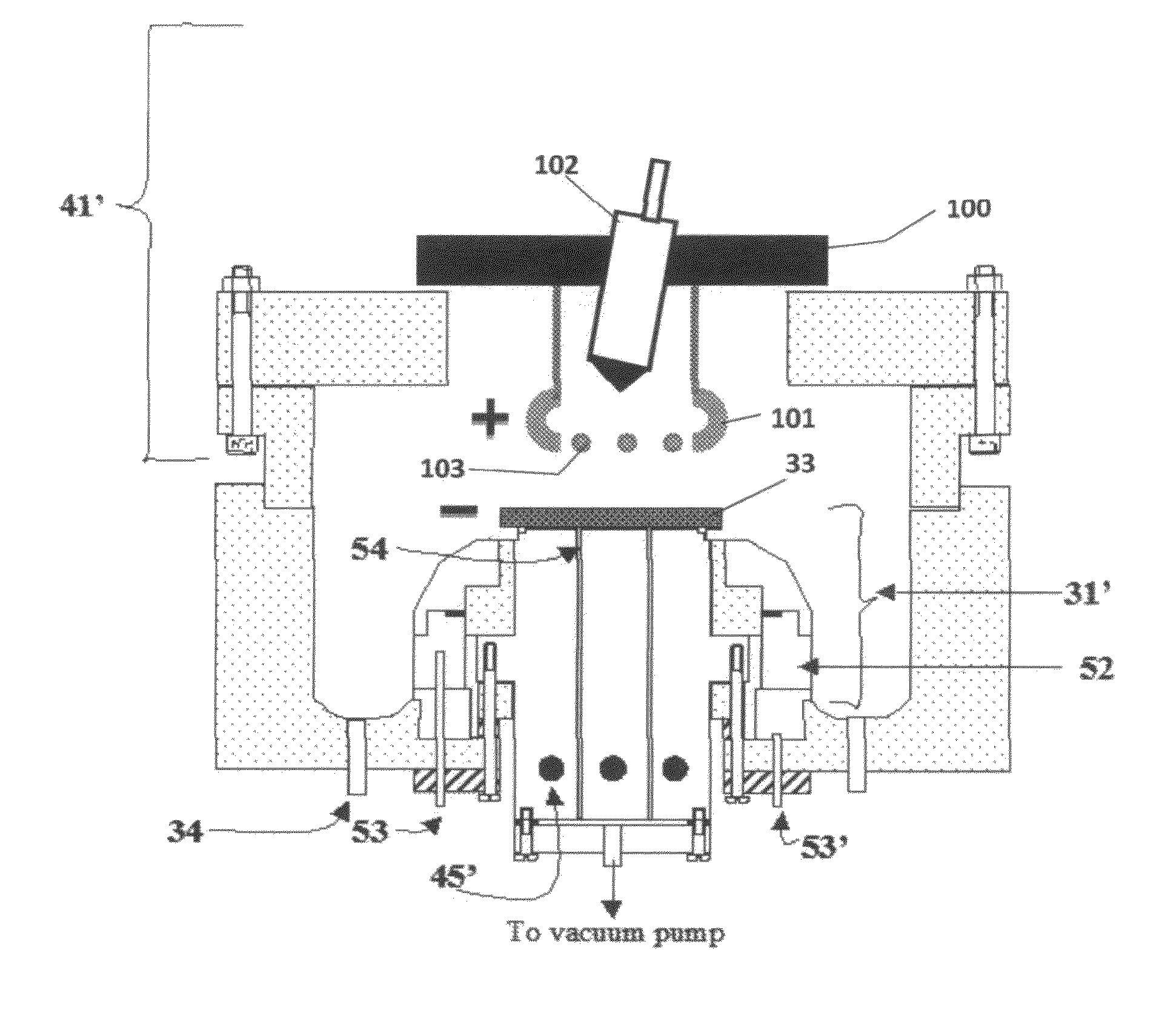
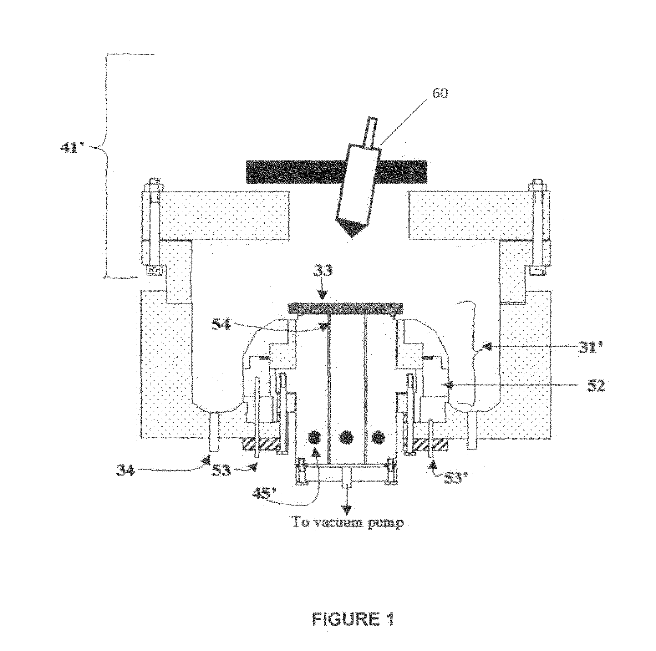
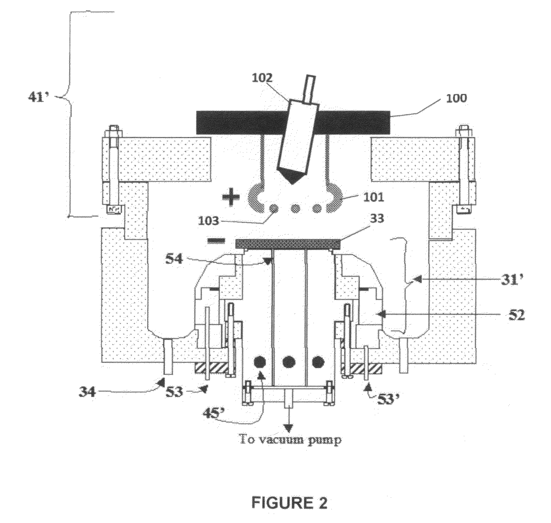
  • Apparatus and method for depositing alkali metals
  • Apparatus and method for depositing alkali metals
  • Apparatus and method for depositing alkali metals

Examples


example

[0091]Referring to FIG. 7, electrolyte matrix 11′ may be deposited on an anode-coated substrate 10′″ as shown earlier in FIG. 6. Li 12 is deposited and reacted as before to form electrolyte 13. Substrate 10′ is coated with cathode material 14 and then a layer of Li-ion conductive adhesive 19 is applied. The adhesive is a reported mixture of polyvinylidene fluoride / hexafluoropropylene copolymer (PVDF / HFP), dissolved in dimethoxyethane (DME), and 1.5M LiPF6 in EC / PC 30% solution heated to 50° C. in closed vessel, then cool to room temperature. The two halves of the cell are hot pressed together using the ion-conductive adhesive 19 to form an ion-conductive mechanical bond, thereby completing the cell. It will be appreciated that the ion-conductive adhesive 19 may alternatively be applied to the anode-coated substrate as shown schematically in FIG. 8.


PUM

PropertyMeasurementUnit
Temperatureaaaaaaaaaa
Electric potential / voltageaaaaaaaaaa

Abstract

A method for making ion conducting films includes the use of primary inorganic chemicals, which are preferably water soluble; formulating the solution with appropriate solvent, preferably deionized water; and spray depositing the solid electrolyte matrix on a heated substrate, preferably at 100 to 400° C. using a spray deposition system. In the case of lithium, the deposition step is then followed by lithiation or addition of lithium, then thermal processing, at temperatures preferably ranging between 100 and 500° C., to obtain a high lithium ion conducting inorganic solid state electrolyte. The method may be used for other ionic conductors to make electrolytes for various applications. The electrolyte may be incorporated into a lithium ion battery.

Description

CROSS-REFERENCE TO RELATED APPLICATIONS[0001]This application is a continuation-in-part of U.S. patent application Ser. No. 12 / 656,000, filed on Jan. 12, 2010, entitled “Film Growth System and Method,” and is also related to U.S. patent application Ser. Nos. 12 / 151,562 filed on May 7, 2008, entitled “Film Growth System and Method,” 12 / 151,465, filed on May 7, 2008, entitled “Zinc Oxide Film and Method of Making,” and 12 / 462,146, filed on Jul. 30, 2009, entitled “Method for Fabricating Cu-Containing Ternary and Quaternary Chalcogenide Thin Films,” all by the present inventor, the entire disclosures of which are incorporated herein by reference. This application is related to U.S. patent application Ser. Nos.______, entitled, “Method of Forming Solid State Electrolyte Having high Lithium Ion Conduction and Battery Incorporating Same”, and ______ entitled Solid State Electrolytes Having High Li Ion Conduction”, and filed on even date herewith by the present inventor, the entire disclos...

Claims


Application Information

Patent Timeline
IPC IPC(8): B05D1/04
CPCC23C18/06Y02E60/122C23C18/1241C23C18/1275C23C18/1279C23C18/1283H01L21/6719H01L21/67207H01L21/6838H01L21/68785H01L29/22H01M4/0419H01M4/1391H01M10/052H01M10/0562H01M10/058H01M2300/0068C23C18/1216Y02E60/10
Inventor OLADEJI, ISAIAH O.
Owner QUANTUMSCAPE CORP
Learn More