
Lithium secondary battery

a secondary battery and lithium ion technology, applied in cell components, electrochemical generators, cell components, etc., can solve the problems of material undergoing a great volumetric change, material pulverizing or peeling off from the negative electrode current collector, and mobile information terminal devices tend to power consumption, so as to inhibit the degradation of charge-discharge performance, and the performance of absorption and release of lithium ions at the surface

Active Publication Date: 2011-07-07
SANYO ELECTRIC CO LTD
View PDF19 Cites 21 Cited by
  • Summary
  • Abstract
  • Description
  • Claims
  • Application Information

AI Technical Summary

Benefits of technology

[0026]It is desirable that the particles of the at least one rare earth compound have an average particle size of from 1 nm to 100 nm.
[0027]The reason why the average particle size of the particles of the rare earth compound is restricted is as follows. The reason why the average particle size of the particles of the rare earth compound is restricted is as follows. If the average particle size exceeds 100 nm, the surface of the lithium-transition metal composite oxide particles cannot be covered densely with the rare earth compound because the particle size of the rare earth compound relative to the particle size of the lithium-transition metal composite oxide particles is too large. As a consequence, the area in which the lithium-transition metal composite oxide particle is directly in contact with the non-aqueous electrolyte and the reductive decomposition product thereof is great, so the oxidative decomposition of the non-aqueous electrolyte and the reductive decomposition product thereof increases. Consequently, the charge-discharge performance degrades. On the other hand, if the average particle size is less than 1 nm, the surface of the lithium-transition metal composite oxide particles is exceedingly covered with the rare earth compound. As a consequence, the performance of absorption and release of lithium ions at the surface of the lithium-transition metal composite oxide particles becomes poor, and the charge-discharge performance degrades. Taking this into consideration, it is more preferable that the average particle size of the particles of the rare earth compound be within the range of from 10 nm to 50 nm.
[0028]The present invention makes it possible to inhibit the reductive decomposition product of the non-aqueous electrolyte from undergoing oxidative decomposition on the positive electrode active material surface. This enables to prevent deposition of the oxidative decomposition product on the surface of the positive electrode active material particles and thereby to inhibit degradation of the charge-discharge performance resulting from the increase of the charge-discharge reaction resistance at the interface between the surface of the positive electrode active material particles and the electrolyte solution. Moreover, the generation of gas, which is a kind of the oxidative decomposition product, can be inhibited, so it is made possible to prevent a battery thickness increase in a flat-type battery. Thus, the present invention can achieve both an improvement in the charge-discharge cycle performance and an increase of the energy density at the same time.

Problems solved by technology

The mobile information terminal devices tend to power consumption as the functions of the devices, such as moving picture playing functions and gaming functions.
In the lithium secondary battery that employs the just-described negative electrode active material, however, the negative electrode active material pulverizes or peels off from the negative electrode current collector because the negative electrode active material undergoes a great volumetric change during absorption and release of lithium.
This causes breakage of the current collection structure in the negative electrode.
As a consequence, electron conductivity within the negative electrode degrades, and the charge-discharge cycle performance becomes poor.
However, even when the current collection capability (electron conductivity) within the negative electrode is improved by the just-described technique, the charge-discharge performance is not improved sufficiently, because a large volumetric change occurs in the silicon during charge and discharge and the resulting fracture in the silicon particle surface causes a considerable degradation in the charge-discharge performance.
The just-mentioned deposition of the oxidative decomposition product increases the charge-discharge reaction resistance at the interface between the surface of the positive electrode active material particles and the electrolyte solution, and it consequently degrades the charge-discharge performance.
In addition, the generation of gas causes the battery thickness to increase, especially in the case of a flat-shaped battery, which results in a decrease in the energy density.
Thus, there is still a problem that the battery performance (especially the charge-discharge cycle performance) degrades considerably when the above-described fractures form in the silicon particle surface.

Method used


Image

  • Lithium secondary battery
  • Lithium secondary battery
  • Lithium secondary battery

Examples


example 1

[0052]A battery fabricated in the same manner as described in the foregoing embodiment was used as the battery of Example 1.

[0053]The battery fabricated in this manner is hereinafter referred to as Battery A1 of the invention.

example 2

[0054]A battery was fabricated in the same manner as described in Example 1 above, except that the heat-treatment temperature for the powder obtained by vacuum filtrating the suspension and further washing it with water was set at 300° C. When the heat treatment is carried out at 300° C., all of or most of the erbium hydroxide changes into erbium oxyhydroxide, so the erbium oxyhydroxide is adhered to the surface of the lithium cobalt oxide particles in a dispersed form. However, a small portion of the erbium hydroxide may remain in the form of erbium hydroxide (without changing into erbium oxyhydroxide), so it is possible that erbium hydroxide may exist on the surface of the lithium cobalt oxide particle. It should be noted that the compound adhered to the surface of the lithium cobalt oxide particles in a dispersed form herein may be referred to as erbium oxyhydroxide, taking into consideration that all or most of the erbium hydroxide changes into erbium oxyhydroxide.

[0055]The batt...

example

Preparation of Positive Electrode

[0076]First, LiOH and a composite hydroxide containing nickel as the main component of the metal elements [Ni0.80Co0.17Al0.03(OH)2] were mixed in an Ishikawa-type Raikai mortar so that the mole ratio of Li to the whole of the transition metals became 1.05:1. Thereafter, the mixture was sintered at 720° C. for 20 hours in an oxygen atmosphere and thereafter pulverized, to thus obtain powder of a lithium-transition metal composite oxide represented as Li1.05Ni0.80Co0.17Al0.03O2 (average particle size 15 μm). Next, erbium oxyhydroxide was adhered to the surface of the lithium-transition metal composite oxide in the same manner as described in Example 2 in the First Group of Examples.

[0077]Next, using the powder of the positive electrode active material in which erbium oxyhydroxide was adhered to the surface, a positive electrode mixture slurry was prepared in the same manner as described in Example 2 in the First Group of Examples above. Thereafter, the...


PUM


Abstract

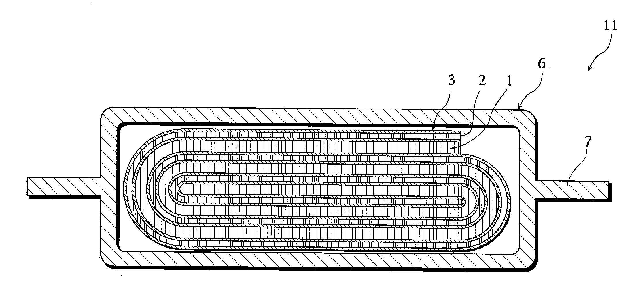
A lithium secondary battery has a positive electrode (1) containing a positive electrode active material having particles of lithium cobalt oxide, a negative electrode (2) containing a negative electrode active material having silicon particles, a separator interposed between the positive electrode (1) and the negative electrode (2), and a non-aqueous electrolyte. Particles of erbium hydroxide or erbium oxyhydroxide are adhered to a surface of the lithium cobalt oxide particles in a dispersed form.

Description

BACKGROUND OF THE INVENTION[0001]1. Field of the Invention[0002]The present invention relates to lithium secondary batteries, and more particularly to improvements of the positive electrode active material in a battery system using a negative electrode active material containing silicon.[0003]2. Description of Related Art[0004]Mobile information terminal devices such as mobile telephones, notebook computers, and PDAs have become smaller and lighter at a rapid pace in recent years. This has led to a demand for higher capacity batteries as the drive power source for the mobile information terminal devices. With their high energy density and high capacity, lithium-ion batteries, which perform charge and discharge by transferring lithium ions between the positive and negative electrodes, have been widely used as a driving power source for such mobile information terminal devices.[0005]The mobile information terminal devices tend to power consumption as the functions of the devices, such...

Claims


Application Information

Patent Timeline
IPC IPC(8): H01M4/36H01M4/485H01M4/50H01M4/525
CPCH01M4/134H01M4/485H01M4/525Y02T10/7011H01M10/0525Y02E60/122H01M4/62Y02E60/10H01M4/48H01M4/58Y02T10/70
Inventor JITO, DAIZOOGASAWARA, TAKESHIFUKUI, ATSUSHI
Owner SANYO ELECTRIC CO LTD
Learn More