
Microfluid-System-Supporting Unit And Production Method Thereof

a microfluid-system support and microfluid-system technology, which is applied in the direction of transportation and packaging, laboratory glassware, instruments, etc., can solve the problems of reducing the flow rate of fluid, and generating surface irregularities of the microfluid-system support uni

Inactive Publication Date: 2011-06-09
RESONAC CORPORATION
View PDF59 Cites 0 Cited by
  • Summary
  • Abstract
  • Description
  • Claims
  • Application Information

AI Technical Summary

Benefits of technology

The present invention provides a microfluid-system-supporting unit that is lower in surface irregularity, more resistant to breakage or deformation, and resistant to positional deviation of the hollow filament. The invention also provides a production method for the microfluid-system-supporting unit. The technical effects of the invention include improved stability and reliability of the microfluid-system-supporting unit, reduced risk of hollow filament breakage or deformation, and reduced contact area between the substrate and the hollow filament.

Problems solved by technology

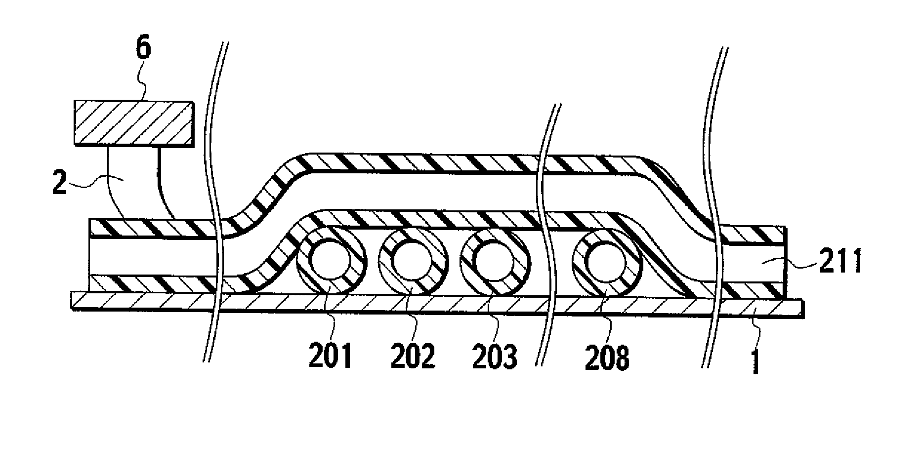
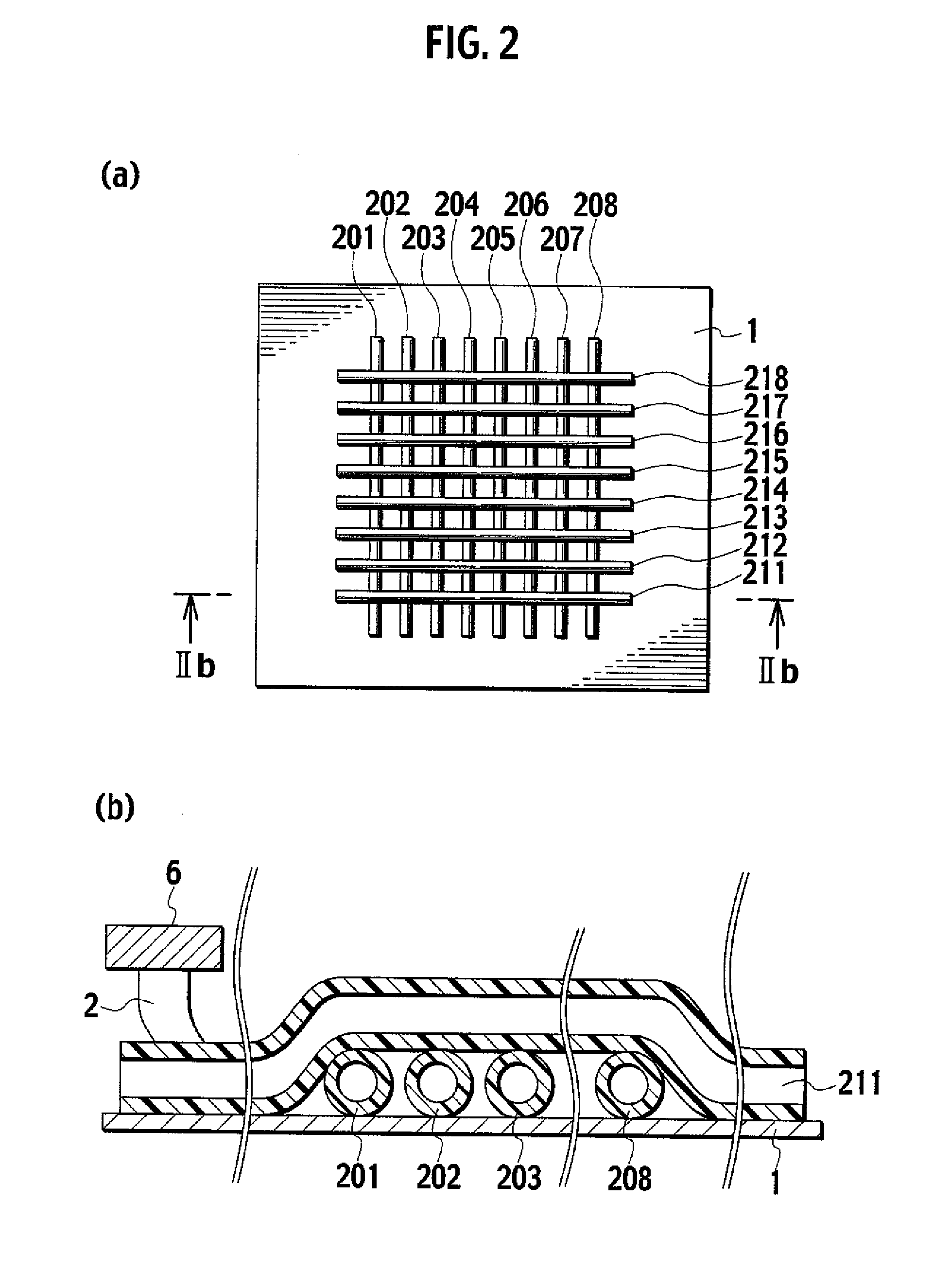
However, the lamination methods described above often resulted in generation of surface irregularity of the microfluid-system-supporting unit, when the specifications on the external diameter of the hollow filaments are different or when there are regions where the hollow filaments cross each other.
Such surface irregularity caused a problem that, when an external force is applied onto the surface of the microfluid-system-supporting unit, the external force accumulates in the raised areas, leading to breakage or deformation of the hollow filament.
Deformation of the hollow filament lead to deformation of the channel shape in the filament, causing problems such as restricted fluid flow and larger pressure drop.
In addition, increase in the number of hollow filaments placed resulted in increase in the number of the intersections between hollow filaments and thus in the number of surface-irregular regions.
In addition, the hollow filaments were fixed less tightly and movable, causing a problem of positional deviation, in the hollow filament-crossing regions, where the substrate and the hollow filaments are in contact with each other with a smaller contact area.

Method used


Image

  • Microfluid-System-Supporting Unit And Production Method Thereof
  • Microfluid-System-Supporting Unit And Production Method Thereof
  • Microfluid-System-Supporting Unit And Production Method Thereof

Examples


example 1

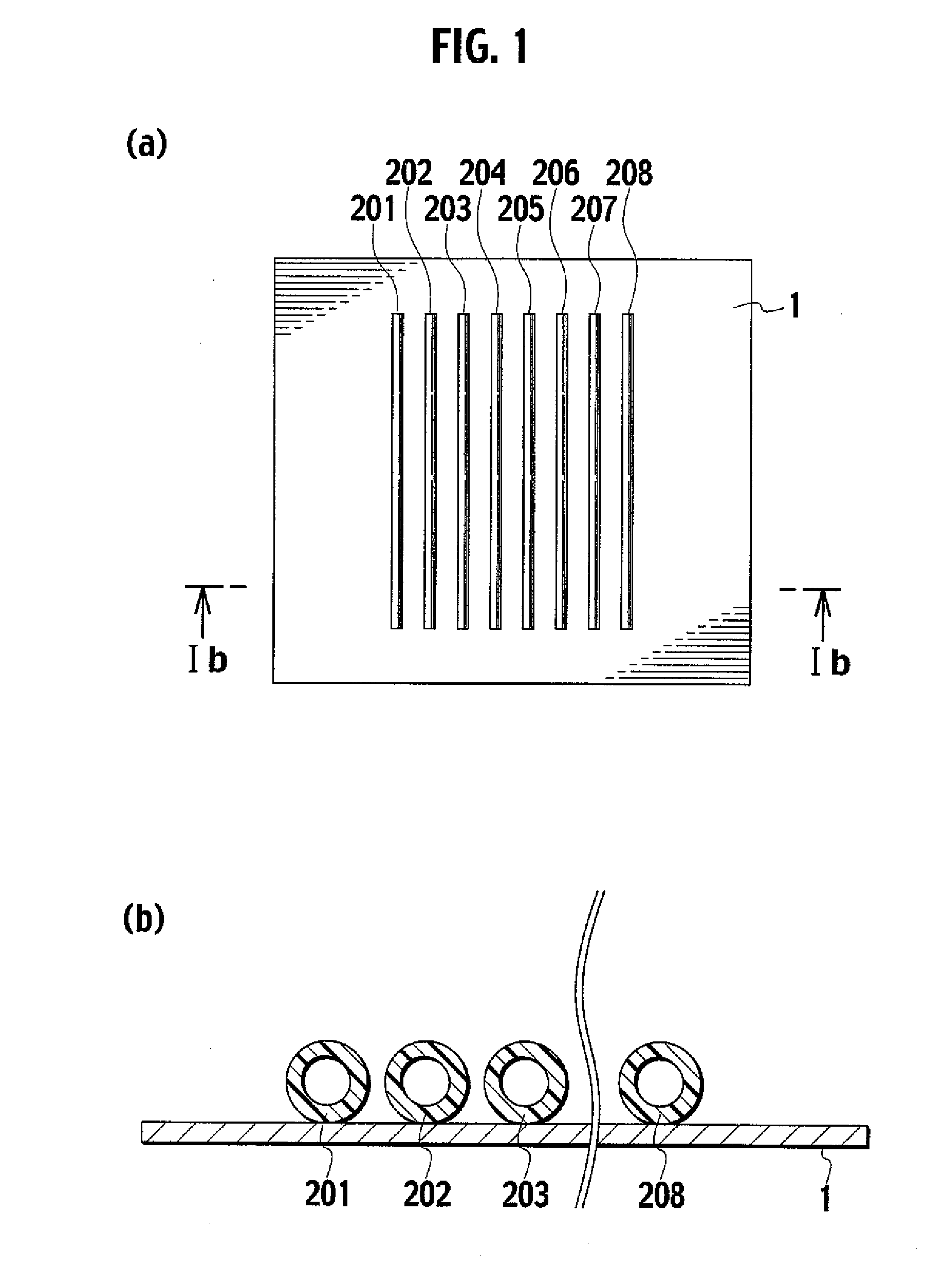
[0209]A double-faced adhesive tape 9415PC (trade name, manufactured by Sumitomo 3M) having a thickness of 0.25 mm was bonded onto one face of a PET film (substrate) having a thickness of 0.05 mm previously cut into a piece of approximately 150 mm in length and 200 mm in width as the intermediate layer having an adhering potential in a roll laminator. A special double tube manufactured by Nitta Moore Company (internal layer: ETFE, external layer: PA11, internal diameter: 1.00 mm, external diameter: 1.50 mm) was made available, and the hollow filament above was placed and fixed on the adhesive layer surface of the double-faced tape in a matrix shape at intervals of 20 mm in the length and width directions. Then, all terminals of the hollow filament in the area approximately 100 mm from the substrate terminal were exposed as the extra-length region. A double-faced tape was bonded at four corners on the other face of the substrate PET film and also into a plastic tray (internal dimensio...

example 2

[0211]An untacky adhesive S9009 (trade name, manufactured by Dow Corning Asia) was applied to a thickness of 0.40 mm at room temperature (25° C.) onto one face of a substrate polyphenylene sulfide (PPS) film (Lumirror, registered trade name, manufactured by Toray Industries, Inc.) having a thickness of 0.06 mm, and the resulting film was cut into a piece of approximately 200 mm in length and 200 mm in width. Then, a PFA-fluorine-resin hollow filament (internal diameter: 0.79 mm, external diameter; 1.53 mm, manufactured by Iwase Co., Ltd.) was made available. The hollow filament of 1 m in length was placed and fixed on the untacky adhesive side of the substrate in a network shape formed by single continuous stroke in an NC wiring machine allowing application of load and ultrasonic wave, and the terminals thereof were exposed out of the substrate as the extra-length regions.

[0212]A polyurethane sealing tape (thickness: 10 mm, width: 15 mm, with adhesive, manufactured by Nitoms Inc.) w...

example 3

[0215]A double-faced adhesive tape (9415PC, trade name, manufactured by Sumitomo 3M) was cut into a piece of approximately 100 mm in length and 200 mm in width, and bonded onto an epoxy resin plate of 110 mm in length, 210 mm in width and 5 mm in thickness with the releasing film facing the epoxy resin plate, and the four corners thereof were fixed with a paper tape. Then, a polyether-imide hollow filament (internal diameter: 0.3 mm, external diameter: 0.5 mm, manufactured by Nirei Industry Co., Ltd.) was made available, and first hollow filaments were placed on the adhesive layer of the double-faced tape in a semicircular pattern at a curvature radius of approximately 20 mm in such a manner that the hollow filaments have a crossing region, in an NC wiring machine allowing application of load and ultrasonic wave. A sponge having a width of 10 mm and a height of 10 mm was made available and bonded to the double-faced tape as the bank in such a manner that it surrounds the hollow fila...


PUM

PropertyMeasurementUnit
internal diameteraaaaaaaaaa
diameteraaaaaaaaaa
light transparencyaaaaaaaaaa

Abstract

The present invention relates to a microfluid-system-supporting unit, comprising a fixing layer formed on a substrate, a protective layer or a fixing layer, wherein part of at least one hollow filament in any shape is placed and fixed in the fixing layer. Thus, it provides a microfluid-system-supporting unit lower in surface irregularity even when there are multiple hollow filaments different in external diameter or the hollow filaments crosses each other and resistant to positional deviation of the hollow filament in the crossing regions, and a production method thereof.

Description

RELATED APPLICATIONS[0001]This application is a divisional application of U.S. Non-Provisional application Ser. No. 11 / 721,361, filed Jun. 11, 2007, which claims the benefit of International Application No. PCT / JP2005 / 022656, filed Dec. 9, 2005, which are hereby incorporated by reference.FIELD OF THE INVENTION[0002]The present invention relates to a microfluid-system-supporting unit having a channel of hollow filament and a production method thereof.BACKGROUND OF THE INVENTION[0003]Studies aimed at reducing the size of reaction systems and analyzers, an application of MEMS (microelectromechanical system) technology, is now in progress in the fields of chemistry and biochemistry, and research and development on monofunctional mechanical components (micromachines) such as micropump and microvalve are now in progress (see, for example, Shoji, “Chemical Industry”, Kagaku Kogyo, April 2001, 52, 4, p. 45-55 and Maeda, “Journal of Japan Institute of Electronics Packaging”, Japan Institute ...

Claims


Application Information

Patent Timeline
Patent Type & Authority Applications(United States)
IPC IPC(8): B32B38/10B32B37/12B32B37/14
CPCB01L3/502707B01L2200/025B01L2200/12B01L2300/0838Y10T428/24612B81B3/0067B81B2201/051B81B2203/0338Y10T428/24752B01L2300/0874Y10T428/249921B81B1/00B81B3/00B01J19/00G01N37/00
Inventor AKAI, KUNIHIKOKAWAZOE, HIROSHI
Owner RESONAC CORPORATION
Learn More