Lithium-oxygen electrochemical cells and batteries
a lithium-oxygen electrochemical cell and battery technology, applied in the direction of fuel cells, primary cells, electrochemical generators, etc., can solve the problems of many obstacles in the utilization of devices as rechargeable cells, system generally exhibits a limited number of recharge cycles, and metals are not suitable for use as anodes, so as to facilitate the reversible interconversion
- Summary
- Abstract
- Description
- Claims
- Application Information
AI Technical Summary
Benefits of technology
Problems solved by technology
Method used
Image
Examples
example 1
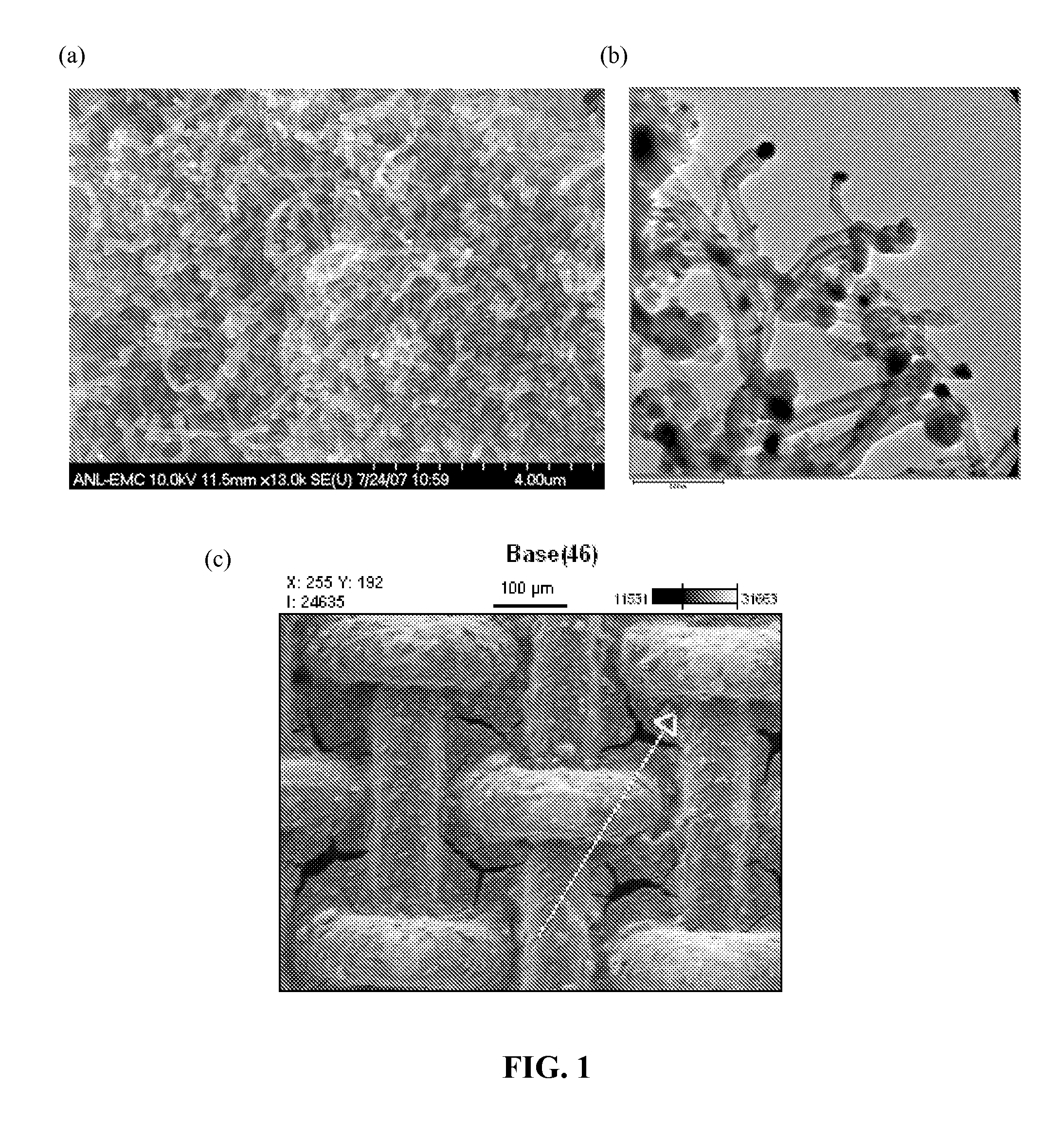
[0034]Carbon nanotubes containing a nanoparticulate cobalt catalyst (Co-CNTs) were prepared via thermal decomposition of low density polyethylene (LDPE) containing about 20 percent by weight (wt %) cobalt acetate (CoAc; Co(C2H4O2)2) catalyst in a sealed autoclave (made up of Haynes 230 alloy) under a nitrogen atmosphere. The autoclave was heated at about 700° C. to about 750° C. for about 2 to 3 hours followed by gradual cooling. The mixture of LDPE and catalyst in the autoclave generated about 50 pounds-per-square inch (psi) of pressure upon heating up to about 680° C., which increased to about 1000 psi at about 700° C. A chemical reaction took place under the autogenic pressure generated in the autoclave during the thermolysis of LDPE in the presence of CoAc, leading to the growth of Co-CNTs in about 40% yield.
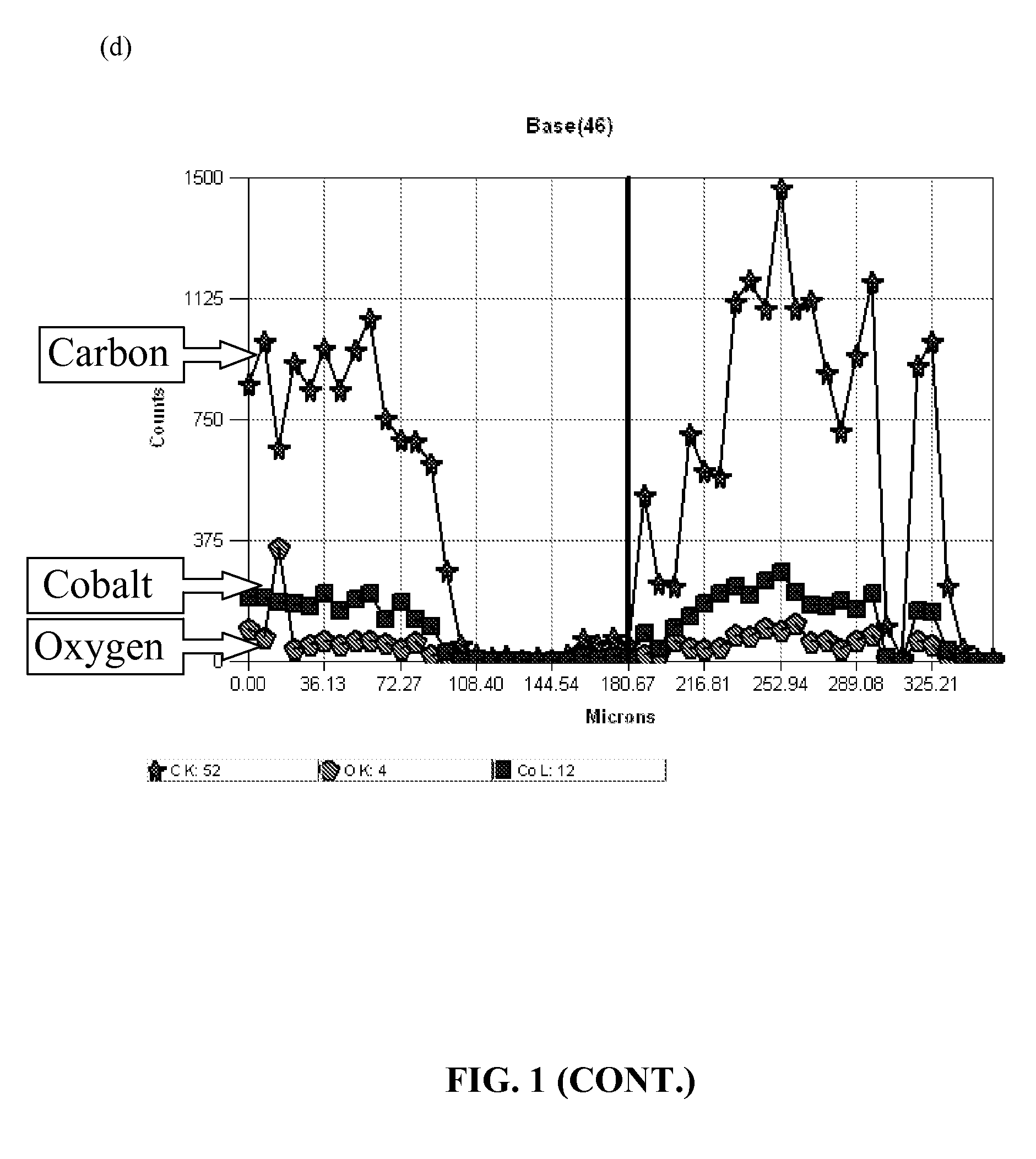
[0035]Panel (a) of FIG. 1 shows a SEM of these carbon nanotubes (CNTs). The dark dots at the tip of the carbon-nanotubes in the SEM are the Co catalyst that was converted to...
example 2
[0037]The coated cathode described in Example 1 was evaluated in a lithium-oxygen electrochemical cell with a lithium metal foil as the anode, and an electrolyte consisting of 1.2M LiPF6 in a 3:7 (w / w) mixture of ethylene carbonate (EC) and ethylmethyl carbonate (EMC), between the anode and the cathode. The cells were assembled in helium-filled glove box. After bringing the lithium-air cell out of the glove box, it was purged with oxygen, and then filled with O2 at about 20 psi pressures. FIG. 2 depicts the electrochemical voltage profiles that were obtained by galvanostatically cycling the cells between about 1.5 V (discharge) and 4.7 V (charge). The observed current density was about 35 mA / g, at a C / 20 rate. Panel (a) shows the first cycle, while Panel (b) shows the second and third cycles. The observed discharge capacity was about 300 mAh / g, and the observed charge capacity was about 800 mAh / g. The average discharge voltage was about 2.5 V, and the average charge voltage was abou...
example 3
[0038]A charge-discharge cycling evaluation was also carried out on cells of the same construction described in Example 2. The cell was galvanostatically discharged and charged between 1.5 V and 4.7 V, respectively. The observed current density was about 75 mA / g at a C / 4 rate, as shown in FIG. 3. The date in FIG. 3 were obtained using a cathode analogous to the one described in Example 2 with C / 4 fast cycling rate; the figure depicts discharge and charge cycle numbers two and three.
PUM
| Property | Measurement | Unit |
|---|---|---|
| tube diameter | aaaaa | aaaaa |
| length | aaaaa | aaaaa |
| length-to-diameter aspect ratio | aaaaa | aaaaa |
Abstract
Description
Claims
Application Information
 - R&D
- Intellectual Property
- Life Sciences
- Materials
- Tech Scout
- Unparalleled Data Quality
- Higher Quality Content
- 60% Fewer Hallucinations
Browse by: Latest US Patents, China's latest patents, Technical Efficacy Thesaurus, Application Domain, Technology Topic, Popular Technical Reports.
© 2025 PatSnap. All rights reserved.Legal|Privacy policy|Modern Slavery Act Transparency Statement|Sitemap|About US| Contact US: help@patsnap.com


