
Soil conditioning disc and configurable disc assembly

a technology of variable discs and soil conditioning discs, applied in soil-working methods, thinning machines, agriculture tools and machines, etc., can solve the problems of increasing production costs, increasing the rate of soil degradation around the globe, and global soil conditions continuing to decline, so as to increase soil oxygenation, reduce evaporation, and enhance soil permeability

Inactive Publication Date: 2011-03-31
WARD KEITH
View PDF20 Cites 5 Cited by
  • Summary
  • Abstract
  • Description
  • Claims
  • Application Information

AI Technical Summary

Benefits of technology

[0018]The present invention is comprised of a soil-conditioning disc and variable system wherein each disc has a series of radially extending geometrically shaped protrusions circumscribing a central hub portion. When the soil conditioning disc system is rolled across the soil surface, a series of consolidated perforations and / or geometric shaped hollows (depending on the particular disc configuration) are created in the soil. This soil conditioning incorporates organic material in the soil and increases soil oxygenation for improved (particularly clay soils) soil health, creates depressional water storage, enhances soil permeability, reduces evaporation, creates even surface water distribution and reduces water runoff. An important purpose of the soil-conditioning disc and system is to enable the soil to retain rain water where it falls, reduce erosion, increase water retention and infiltration of the soil and to improve soil quality.

Problems solved by technology

Soil health has declined steadily for a number of years and, coupled with the high rates of soil erosion, its rate of degradation is increasing around the globe.
There have been many attempts to address this situation in recent years, but global soil conditions continue to decline.
However, there are several disadvantages associated with No-Till.
No-Till requires the use of herbicides to eliminate competition from weeds and progressively increasing amounts of fertilizer, which simply raises production costs and not to mention pollution; the heavy residue left on the soil surface hinders soil warming and drying, rendering planting more difficult and resulting in poor seed-to-soil contact, thus reducing seed germination; and the soil surface is also left with a very low permeability, resulting in rain water runoff and reduced infiltration to subsurface soils thereby reducing aquifer recharge.
While No-Till was developed to minimize soil erosion, which it does effectively, the lack of water management allows excess surface water from rainfall to run-off and, in fact, is often directed away from the field into nearby waterways in an attempt to stop ponding / flooding.
In contrast to No-Till, tilling the soil with disc harrows, field cultivators, and other similar equipment leaves the soil in a highly erodible condition.
Thus, neither system is very effective at “water management” and, in the case of tilled soil, some form of erosion control needs to be employed.
The concavity of the discs, as well as their being offset causes them to loosen and pickup the soil they cut.
There are several problems however with offset disc harrows.
First, such an implement requires high horsepower due to the way in which the machine functions.
Second, the shearing / scraping action created by the disc implements as they are dragged sideways across the soil causes “smearing” to the ground under the discs work area.
Third, the disc harrow leaves the soil in a “highly erodible” condition.
There are several other types of tillage equipment that also have “discs” as part of a “multi-tool” soil preparation system, such as “disc-rippers” and “field cultivators.” Globally, there are some highly erodible soils that are very fertile, extremely fragile and very difficult to manage due to their high organic content.
The use of a Disc Harrow machine in such soils is ill-advised; however, farmers have had little choice in the past.
When the soil is compressed to such a level that it becomes impervious to water, the soil below this point is effectively sealed off from water and oxygen, obstructing the soils ability to produce good crops.
Too large a force will squeeze the soil until it becomes compacted.
When the degree of compaction is severe, from a practical standpoint it is considered to be a compaction problem.
In the case of “imprinting and impressing” or “punching and compacting,” the soil is compacted in the first instance, therefore reducing the amount of soil particles that can be dislodged by water impact; however, such systems also reduce the soil's infiltration capability.
However, such a system suffers from the loose particles of soil and organic matter being washed into the bottom of the pool, thereby capping or sealing the soil surface.
Once the pools are sealed or capped, over-topping quickly occurs.
By definition, when the pools or reservoirs created by conventional systems are full, they are already close to failing.
Therefore, any water that starts to build up in the pools or reservoirs is exceeding the infiltration rate of the soil, eventually ending in over-topping and the inevitable loss of top soil by erosion.
In addition, even after farmland has been prepared with some form of erosion control, surrounding land that may have been left fallow as part of a rotation, or a government incentive program, may not have had any form of erosion control.
If this unprepared land is higher than the prepared land, it is likely that surface water run-off will occur, causing damage and erosion to the prepared farm land.
However, although these later-designed machines are lighter in weight than the Dixon Wheel and other similar devices, they are all still relatively heavy, and in some instances have to operate as a stand alone piece of equipment.
Traditionally, RTS machines operate at a very slow pace due to the manner by which they operate.
However, imprinting-type RTS machines, which impress or compact the soil surface into the required shape to form reservoirs, generally travel fast, i.e., 5 to 6 mph.

Method used


Image

  • Soil conditioning disc and configurable disc assembly
  • Soil conditioning disc and configurable disc assembly
  • Soil conditioning disc and configurable disc assembly

Examples


Embodiment Construction

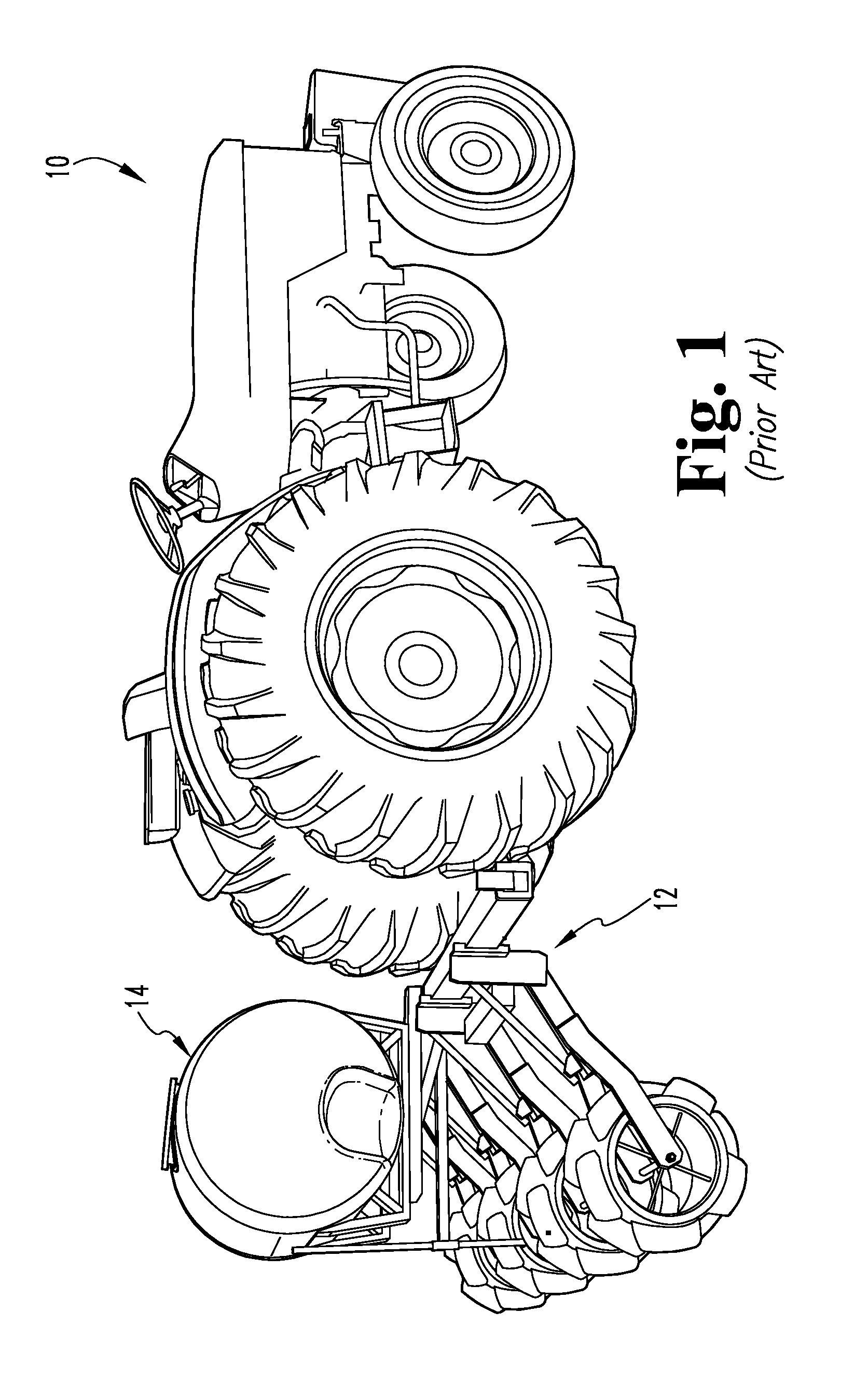
[0050]FIG. 1 shows a conventional arrangement of a piece of farm machinery (tractor) 10 pulling a farm implement 12 for treating or managing the crop field soil. Applicant's soil-conditioning disc and variable disc assemblies are preferably similarly intended to be carried by a farm implement 12 and can either be pulled or pushed over the soil. Farm implement 12 can further be equipped with a seed hopper or fertilizer tank 14 well known in the art.

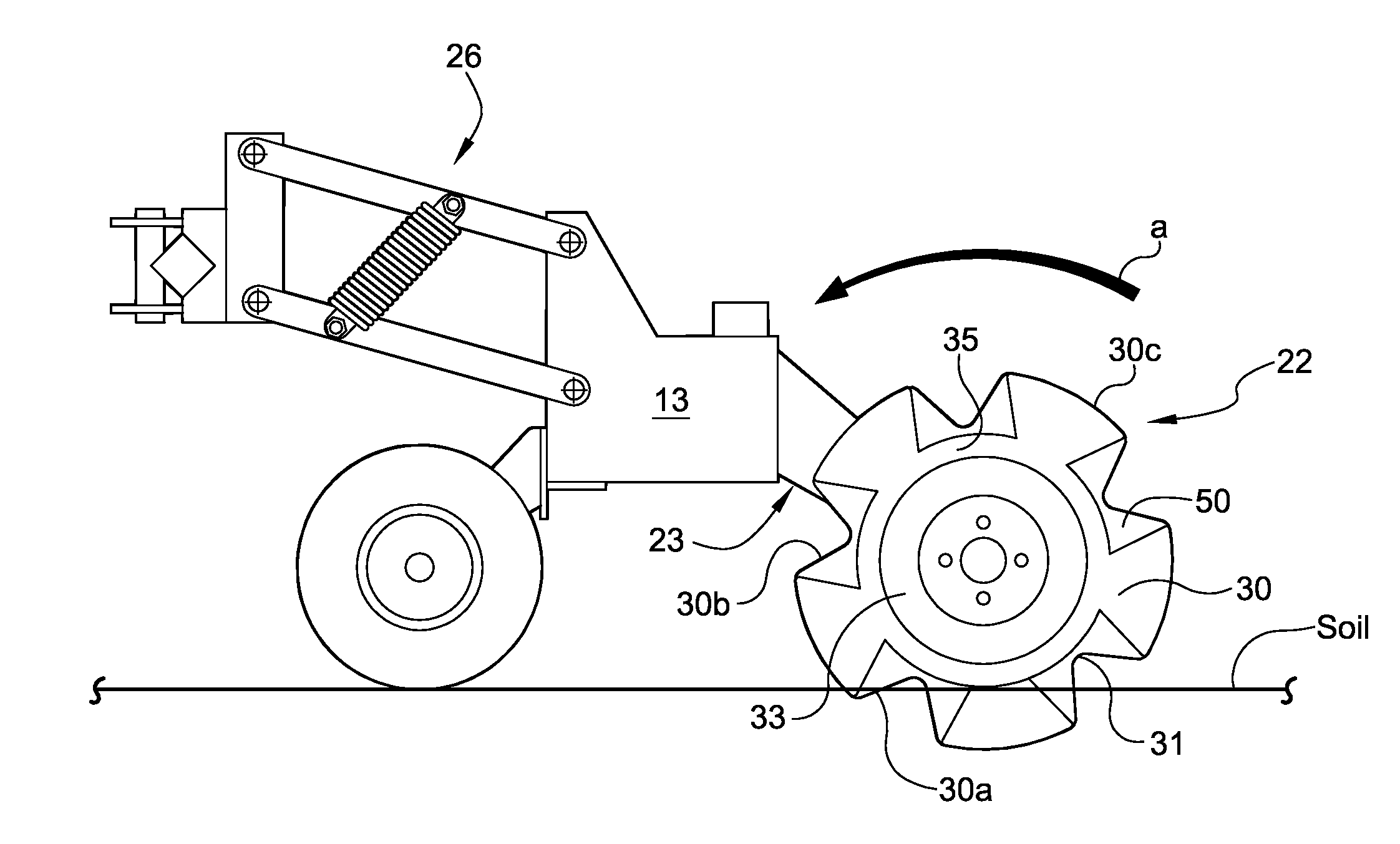
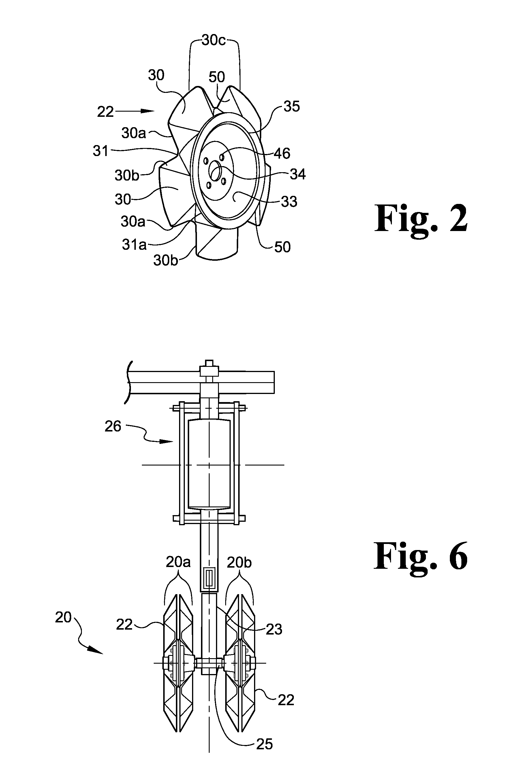
[0051]FIGS. 2, 3A and 3B show a preferred embodiment of the disc 22 provided by this invention comprising a generally star-shaped member having multiple (preferably at least two) peripheral extensions or protrusions 30 that extend radially outwardly from a central hub portion 32 having a central opening 34. As shown in FIG. 3B, disc 22 has a first side 22a, a second opposing side 22b, a central axis 22′ and a longitudinal axis 22″. The disc of this invention can have more or less peripheral extensions depending on a greater or smaller diam...


PUM


Abstract

A soil-conditioning disc and variable disc assembly system is presented wherein each disc has a series of radially extending geometrically shaped protrusions with intermittent cutting edges and consolidation surfaces, all circumscribing a central hub portion. The disc can be used individually or in multiplicity in a variety of configurations as appropriate for the soil conditions and soil-conditioning task at hand. When the soil-conditioning disc is rolled across the soil surface, a series of consolidated perforations and / or geometric-shaped hollows and restricting channels (depending on the particular disc configuration utilized) are created in the soil. This soil-conditioning disc and assembly simultaneously cuts and incorporates organic material into the soil to increase soil oxygenation for improved soil health, to create depressional water storage, to enhance soil permeability, to reduce evaporation, and to improve surface water distribution by reducing runoff.

Description

CROSS-REFERENCE TO RELATED APPLICATIONS[0001]This application claims priority to earlier-filed U.S. provisional patent application Ser. No. 61 / 246,324, filed Sep. 29, 2009.FIELD OF THE INVENTION[0002]This invention relates to soil conditioning devices, and more particularly relates to a novel disc and a variable disc assembly and methods for tilling, cutting and laterally consolidating the soil while avoiding harmful compaction, thereby increasing infiltration, conserving moisture and reducing soil erosion.BACKGROUND OF THE INVENTION[0003]Soil health has declined steadily for a number of years and, coupled with the high rates of soil erosion, its rate of degradation is increasing around the globe. For this trend to stop and our soils to recover, new equipment and new farming practices need to be developed and adopted that improve soil and water management. The earth is losing topsoil and water aquifer levels are falling at alarming rates. Governments around the world are imposing so...

Claims


Application Information

Patent Timeline
Patent Type & Authority Applications(United States)
IPC IPC(8): A01B39/08A01B79/00A01B7/00
CPCA01B35/16A01C7/006A01B35/28Y02P60/20
Inventor WARD, KEITH
Owner WARD KEITH
Learn More