Thermally improved lamp

a technology of thermal stability and lamp, applied in the field of thermal improvement of lamps, can solve the problems that lamp parts, in particular shafts or power supply lines, can also exhibit temperature-dependent degradation phenomena, and achieve the effects of high power levels, good adhesion, and sufficient long-term and thermal stability

Inactive Publication Date: 2011-03-03
OSRAM GMBH
View PDF9 Cites 0 Cited by
  • Summary
  • Abstract
  • Description
  • Claims
  • Application Information

AI Technical Summary

Benefits of technology

[0019]The material used for the coating can be, in particular, the metals aluminum, platinum, iridium, tungsten, nickel, titanium, preferably chromium and alloys, mixtures and multiple layers thereof. According to the invention, the electrical conductivity of the material is needed so that ITO (indium tin oxide) or electrically conductive nanoparticles are also conceivable as the coating, for example, in addition to the conventional metals listed above. The electrically conductive materials chosen are expediently substances which can be applied as a uniform and homogeneous layer with good adhesion and have a sufficient long-term and thermal stability.
[0020]The invention can particularly advantageously be applied in the case of halogen lamps and particularly preferably high-pressure gas discharge lamps, preferably those with particularly high power levels. The reduction in temperature of the lamp shaft, which is achieved with the coating according to the invention, serves not only to increase the service life of the lamp, but also makes it possible to reduce the size of the lamp. The optimization of the power / size ratio made possible by the invention is particularly important, for example, for projection lamps. Furthermore, the invention is also advantageous for film lighting, photographic lighting and stage lighting. High lamp powers are desirable for these applications.
[0021]Finally, the invention relates to the production of a lamp having the coating according to the invention. Technical processes that are customary for applying coatings are spraying, sputtering, vapor deposition or an immersion bath, these processes including those where a previously applied layer is thinned to the desired layer thickness. One preferred process is ICPECVD (inductively coupled plasma enhanced chemical vapor deposition). This process makes it possible to deposit a metal, which was previously supplied as a metal hydride gas, by means of a plasma in a controlled process that makes it possible to precisely control the layer thickness arising on the lamp vessels, in particular by the application of a plurality of layers each with a self-limited thickness.

Problems solved by technology

Lamp parts, in particular shafts or power supply lines, can also exhibit temperature-dependent degradation phenomena if other materials are used.

Method used


Image

  • Thermally improved lamp
  • Thermally improved lamp
  • Thermally improved lamp

Examples


Embodiment Construction

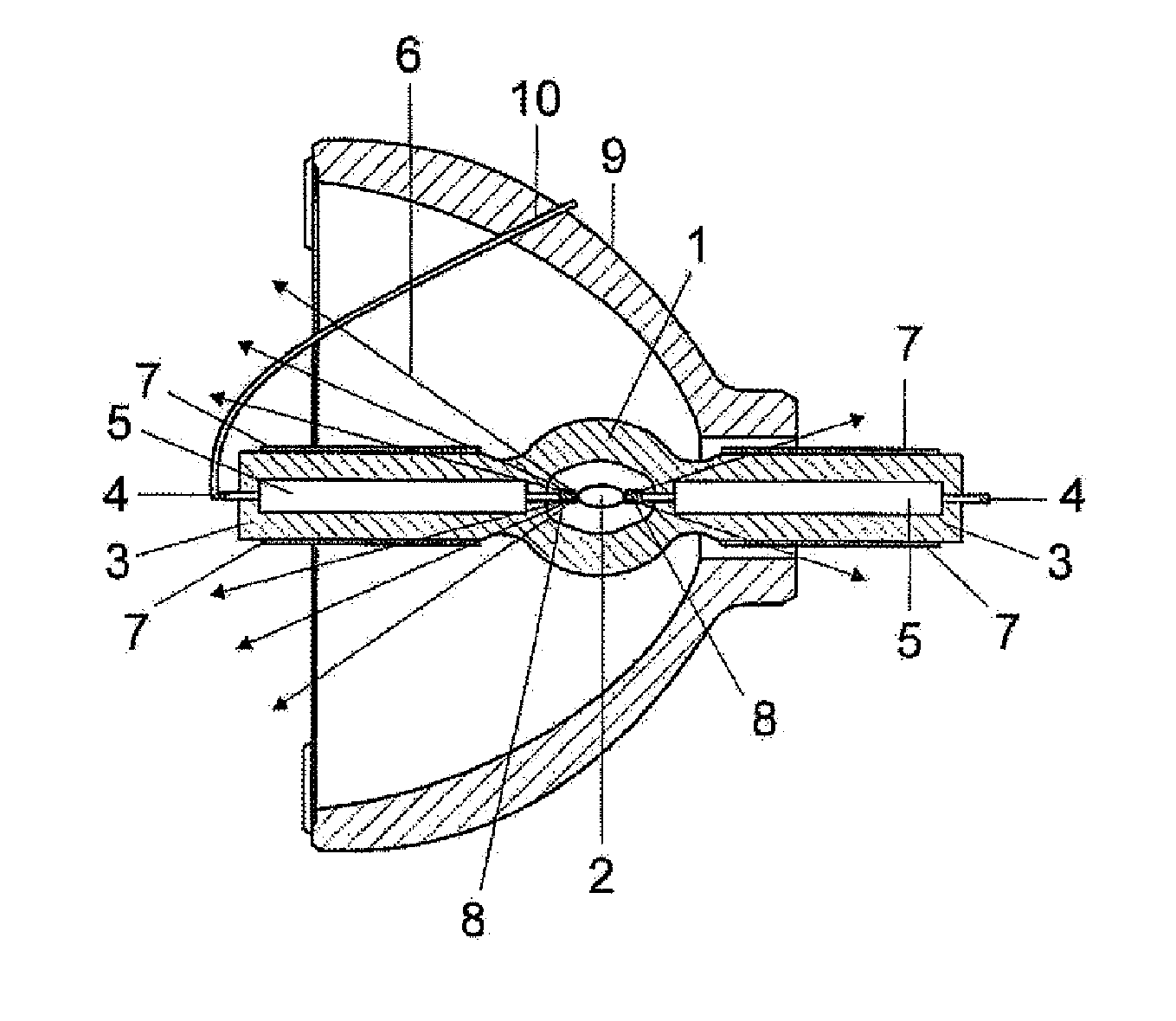
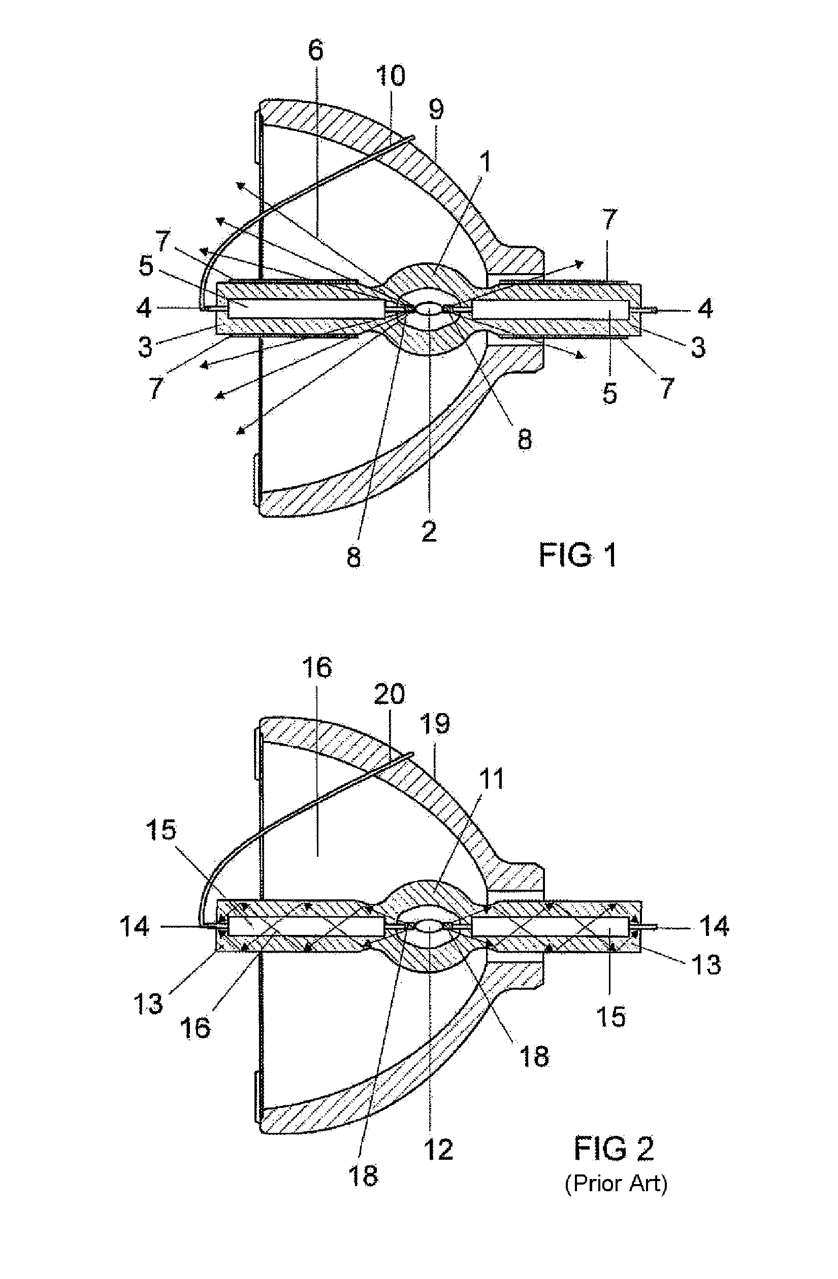
[0028]FIG. 1 shows a schematic illustration of a high-pressure gas discharge lamp according to the invention having a reflector 9. For comparison, FIG. 2 shows a lamp having a reflector 19 from the prior art. The lamp vessels 1, 11 of the two lamps are produced from quartz glass and each have two shafts 3, 13 on opposite sides. The power supply lines 4, 14 are routed through the ends of the shafts 3, 13, and the power supply lines 4, 14 within the reflectors 9, 19 are routed with extensions 10, 20 onto the outer side of the reflectors 9, 19. The lamp housings 1, 11 are sealed on molybdenum films 5, 15 in the power supply lines 4, 14 within the shafts 3, 13.

[0029]In this type of lamp, an arc 2, 12 between the electrodes 8, 18 represents the light source. This arc 2, 12 is likewise the source of the infrared radiation 6, 16, which is denoted symbolically by arrows.

[0030]Supplementarily to the lamp in FIG. 2, FIG. 1 shows the coating 7 according to the invention on the outer side of th...


PUM


Abstract

A lamp having a lamp vessel is provided, the lamp vessel having a shaft, through which a power supply line extends; and a metallically conductive coating on the outer side of the shaft, wherein the maximum layer thickness of the coating is 30 nm, and the layer thickness is designed to minimize the reflection of infrared radiation generated in the lamp.

Description

TECHNICAL FIELD[0001]This invention relates to an electric lamp, for example a high-pressure gas discharge lamp or a halogen incandescent lamp.PRIOR ART[0002]An important criterion in the design of a lamp, for example a halogen lamp or a high-pressure gas discharge lamp, is the heat balance. The thermal radiation generated in the lamp is particularly important.[0003]Common designs of the lamp vessel, which is preferably produced from quartz glass, have one to two shafts through which the power supply lines are routed. Molybdenum film is preferably used in the power supply lines for reasons of sealing, and this film ages increasingly quickly owing to oxidation above a critical temperature. Lamp parts, in particular shafts or power supply lines, can also exhibit temperature-dependent degradation phenomena if other materials are used.[0004]In the case of a lamp as proposed in U.S. Pat. No. 6,084,352, a coating which readily conducts heat and also has a high thermal emissivity is employ...

Claims


Application Information

Patent Timeline
Patent Type & Authority Applications(United States)
IPC IPC(8): H01J5/08H01J9/00
CPCH01K1/32H01J61/35
Inventor KROELL, JOSEF
Owner OSRAM GMBH
Why Eureka
Try Eureka