Camera Adapter Based Optical Imaging Apparatus

a technology of optical imaging and adapter, applied in the field of optical imaging apparatuses and adapters based on camera adapters, to achieve the effect of reducing nois

Active Publication Date: 2011-02-24
UNIVERSITY OF KENT
View PDF6 Cites 294 Cited by
  • Summary
  • Abstract
  • Description
  • Claims
  • Application Information

AI Technical Summary

Benefits of technology

[0025]The present application also describes methods and devices to produce depth resolved information and images using colour cameras which can be extended to specialised systems for speed of operation and versatility.
[0027]In keeping with the invention, a much lower cost solution is provided which employs the elements in any commercially available camera to achieve different functionality. In order to make use of such elements, the present invention provides different versions of adapters which transform a camera (or suits several cameras to be transformed) into specialized imaging instruments.
[0036]In a ninth aspect, the present invention relates to an adapter which is based on channelled spectrum low coherence interferometer where in order to avoid saturation of a separate confocal receiver due to the reference beam, the reference beam in the interferometer is shifted laterally relatively in relation to the object beam before hitting the spectrometer. The dispersing element in the spectrometer may utilize diffraction or dispersion, i.e. it may employ a diffraction grating or a prism to angularly deflect the rays according to their wavelength or frequency. When a diffraction grating is used, the two interferometer beams, object and reference are slightly laterally shifted and the light in the zero order from the object beam is sent towards the CM (SLO) channel and the light in higher diffraction orders serves producing the A-scan OCT image by interference on the sensor array. When using a prism, reflection from one facet of the prism is used to divert light from the object beam towards a CM (SLO) receiver while the two beams, object and reference, are laterally shifted, then suffer dispersion and then interfere on the sensor array. The invention uses an optimised lateral shift of the two beams. The shift value is a minimum to ensure that no reference beam penetrates the CM (SLO) aperture in either case of the dispersing element mentioned above, diffraction grating or prism, and not too large to avoid the decrease in the spectrometer sensitivity due to the spectrometer resolution. In this way, simultaneous measurement of intensity of light using the confocal receiver with the A-scan OCT provided by the sensor array is made possible. The adapter may also include a device or devices for phase modulation or frequency shifting to provide means for full range CS-OCT, where the mirror terms are eliminated by constructing the complex Fourier transformation.
[0038]In a tenth aspect, the invention provides an optical configuration with minimal losses where a 50 / 50 beamsplitter is used to create two shifted object and reference beams for two cameras which are assembled in the adapter to operate in CS-OCT regime.
[0039]The lateral shift of the two beams can be customised for two possible goals: (i) to eliminate the noise due to autocorrelation terms in each arm of the OCT interferometer, eliminate the zero frequency and the mirror terms which lead to ghost images for OPD values of the same modulus but opposite sign; (ii) by adding confocal receivers, where the two object beams, output of the beamsplitter are subject to no spectral analysis and are summed up in the confocal receivers, while the object and reference beams are spectrally analysed by each spectrometer and their results is subtracted, and where the lateral shift of the object and reference beams prior to the 50 / 50 beamsplitter is just sufficient to displace the reference beam out of the input apertures of the two confocal receivers. In this aspect, variations are admitted in the form of: (i) using a 2D transversal scanner to scan a flying spot over the object to be measured or imaged, with the two confocal receivers employing point photodetectors and (ii) using a 1D transversal scanner to scan an illuminating line over the object, in which case the confocal receivers use two other 2D cameras utilised as line cameras, or the confocal receivers use line cameras, where in either case such system provides simultaneously an en-face image (microscopy or eye fundus) with volume collection of multiple B-scans OCT images.

Problems solved by technology

As another disadvantage, the photodetector array and the source are placed within the same compact spatial block and assembled to accomplish photography, a different function than that envisaged by the present application.

Method used


Image

  • Camera Adapter Based Optical Imaging Apparatus
  • Camera Adapter Based Optical Imaging Apparatus
  • Camera Adapter Based Optical Imaging Apparatus

Examples


Embodiment Construction

[0053]Various features of the present invention, as well as other objects and advantages attendant thereto, are set forth in the following description and the accompanying drawings in which like reference numerals depict like elements.

1. Fundus Camera

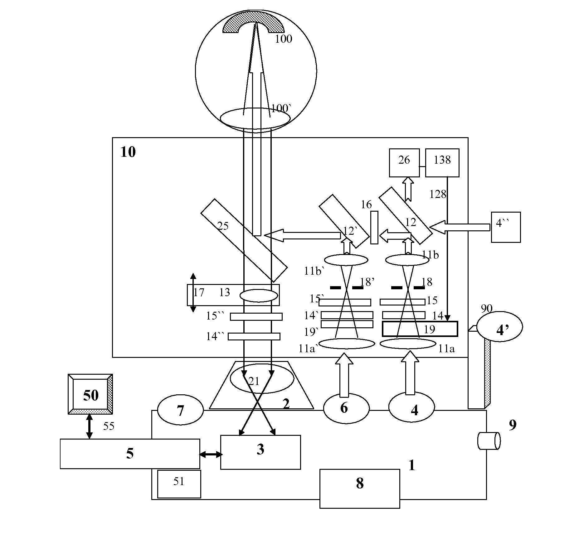
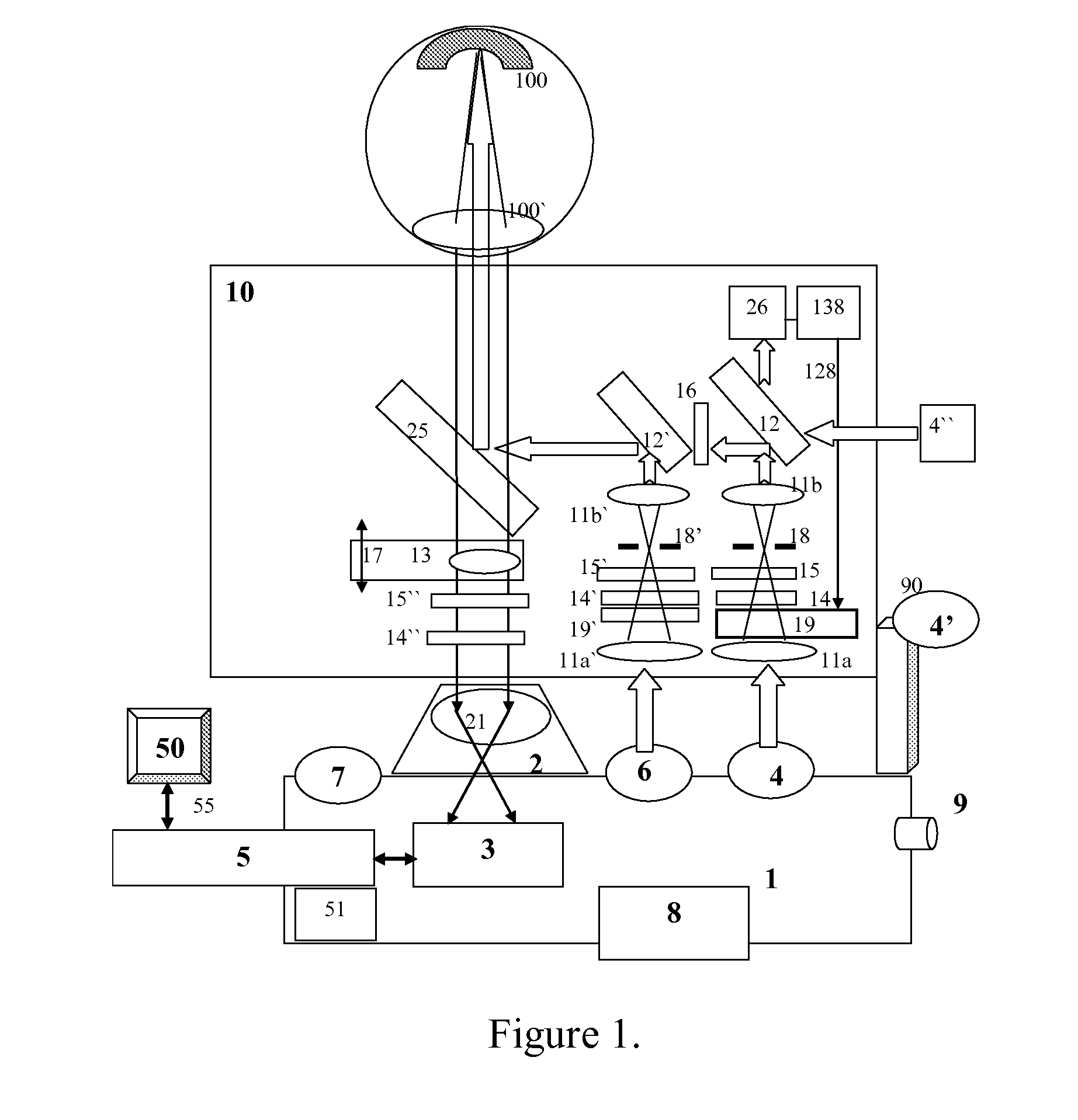
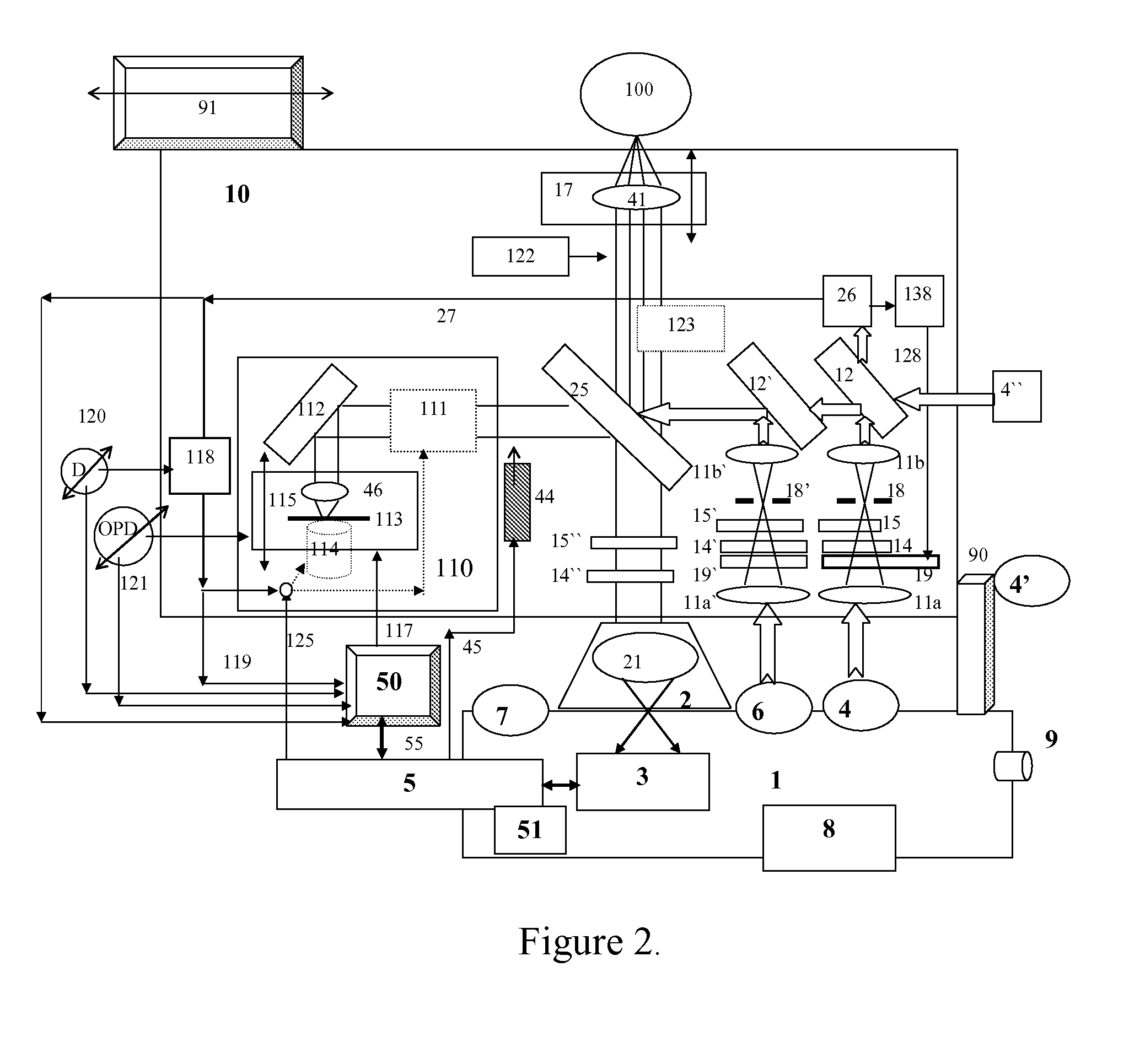
[0054]A fundus camera for imaging the retina, as well as OCT imagers involve and make use of techniques known in the art, to produce images using CCD cameras or arrays of photodetectors. They use optical sources and special interfaces to image the retina and transfer the reflected light into a 2D pattern projected on the CCD array. By adding a reference beam to the beam conveying the 2D information carried by the object beam reflected from the target, a full field or a coherence radar OCT system is obtained. In order to adjust the position in depth where the image is collected from, the OCT systems have means for longitudinal scanning of the reference path length, have means for controlling the phase and polarization in order to maximiz...


PUM


Abstract

The invention describes several embodiments of an adapter which can make use of the devices in any commercially available digital cameras to accomplish different functions, such as a fundus camera, as a microscope or as an en-face optical coherence tomography (OCT) to produce constant depth OCT images or as a Fourier domain (channelled spectrum) optical coherence tomography to produce a reflectivity profile in the depth of an object or cross section OCT images, or depth resolved volumes. The invention admits addition of confocal detection and provides simultaneous measurements or imaging in at least two channels, confocal and OCT, where the confocal channel provides an en-face image simultaneous with the acquisition of OCT cross sections, to guide the acquisition as well as to be used subsequently in the visualisation of OCT images. Different technical solutions are provided for the assembly of one or two digital cameras which together with such adapters lead to modular and portable high resolution imaging systems which can accomplish various functions with a minimum of extra components while adapting the elements in the digital camera. The cost of such adapters is comparable with that of commercial digital cameras, i.e. the total cost of such assemblies of commercially digital cameras and dedicated adapters to accomplish high resolution imaging are at a fraction of the cost of dedicated stand alone instruments. Embodiments and methods are presented to employ colour cameras and their associated optical sources to deliver simultaneous signals using their colour sensor parts to provide spectroscopic information, phase shifting inferometry in one step, depth range extension, polarisation, angular measurements and spectroscopic Fourier domain (channelled spectrum) optical coherence tomography in as many spectral bands simultaneously as the number of colour parts of the photodetector sensor in the digital camera. In conjunction with simultaneous acquistion of a confocal image, at least 4 channels can simultaneously be provided using the three color parts of conventional color cameras to deliver three OCT images in addition to the confocal image.

Description

FIELD OF THE INVENTION[0001]This invention relates to a method and apparatus for imaging transparent objects in general and tissue in particular using digital cameras. The invention describes several adapters which can make use of the devices in commercial digital cameras to accomplish different functions, such as a fundus camera, or as an en-face optical coherence tomography (OCT) or as a channelled spectrum (Fourier domain) optical coherence tomography (CS-OCT), or as a non-invasive dual channel optical imaging instrument which can be used to provide simultaneous cross section OCT images and compound en-face images. In microscopy, the system delivers simultaneously cross sections from specimens and en-face oriented confocal microscopy (CM) images. If used for imaging the retina of the eye, then the system delivers simultaneously two images, OCT cross sections from the retina and en-face oriented fundus images, of the type delivered by a scanning laser ophthalmoscope (SLO) or a con...

Claims


Application Information

Patent Timeline
IPC IPC(8): H04N5/262H04N5/225
CPCA61B3/102H04N5/33G02B21/0064G01B9/0203G01B9/02079G01B9/02007G01B9/02091G01B9/02049G01B9/02069G01B2290/70G01B2290/35A61B3/14H04N5/2252H04N5/232G02B21/0056H04N23/20H04N23/51
Inventor PODOLEANU, ADRIAN
Owner UNIVERSITY OF KENT
Why Eureka
Try Eureka