
Sintered porous structure and method of making same

Inactive Publication Date: 2011-02-10
RGT UNIV OF CALIFORNIA
View PDF2 Cites 24 Cited by
  • Summary
  • Abstract
  • Description
  • Claims
  • Application Information

AI Technical Summary

Benefits of technology

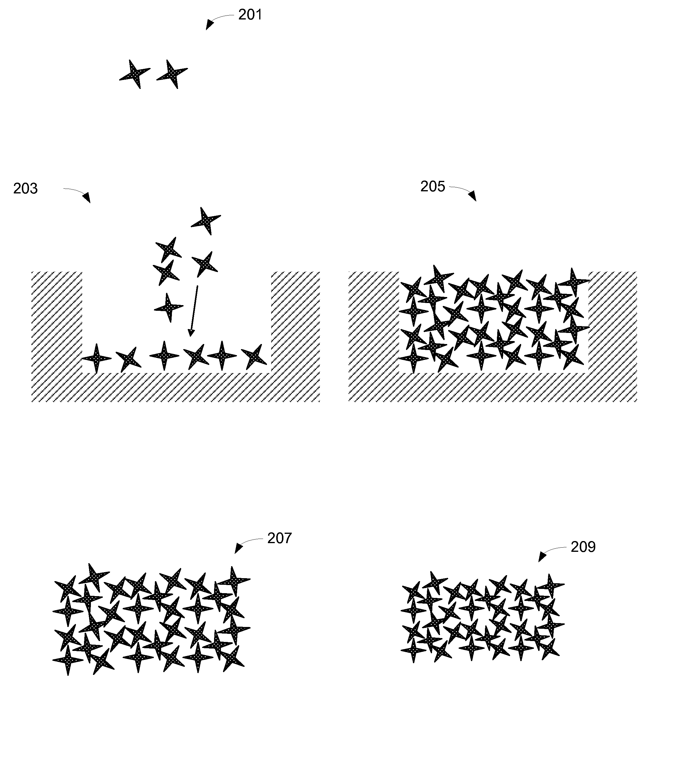
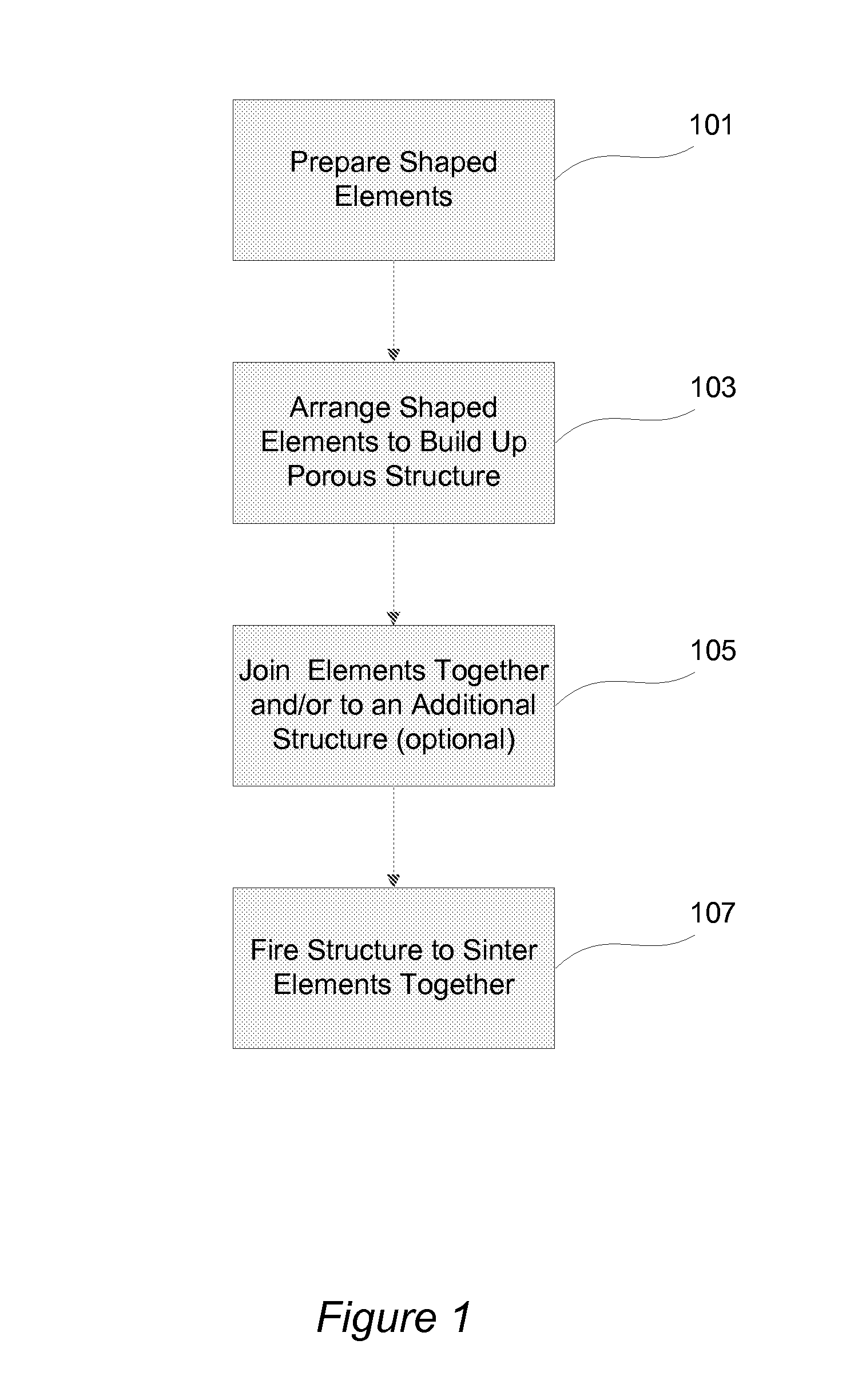
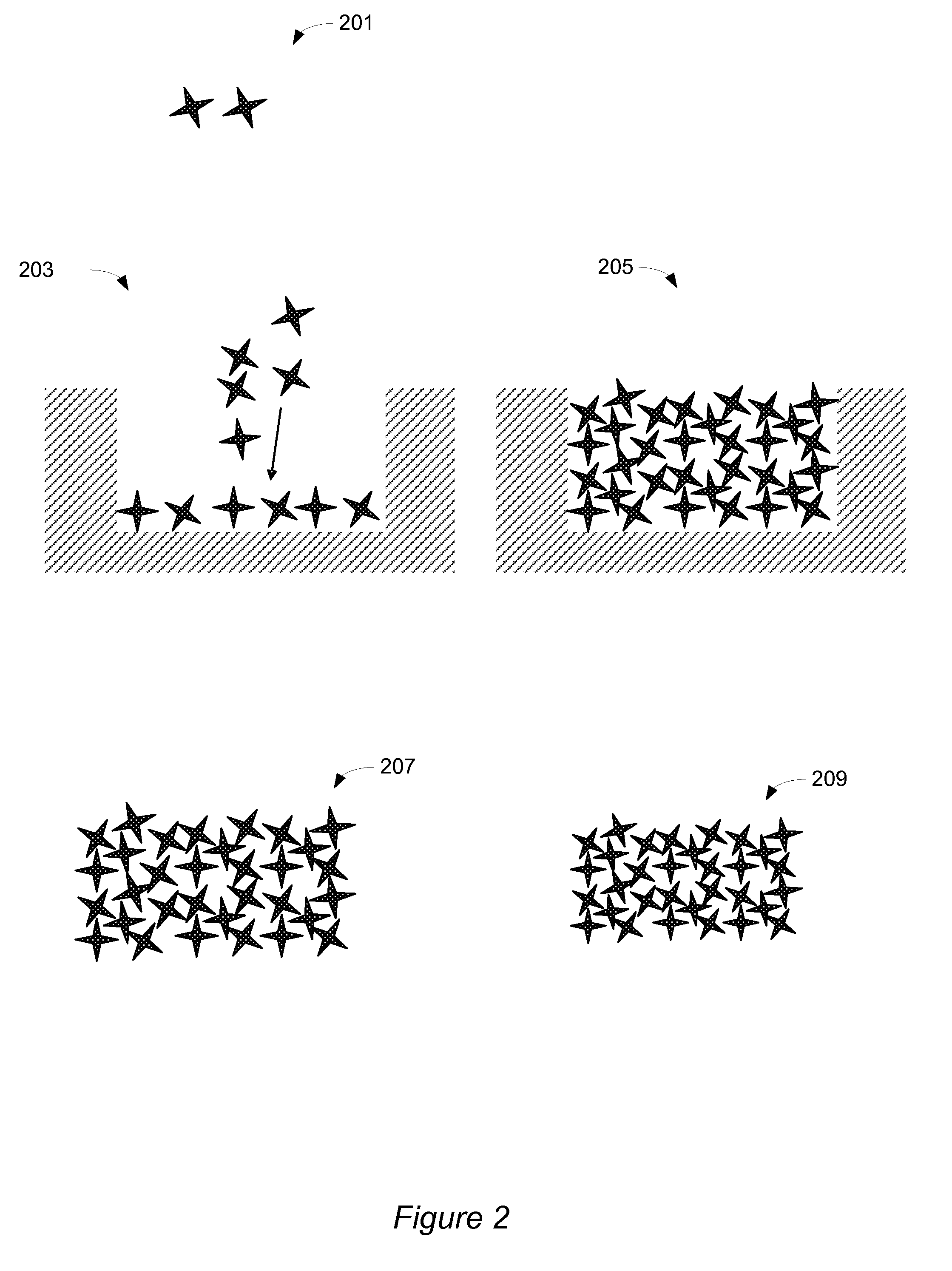
[0009]Simple, low cost methods of manufacturing highly porous structures are provided. The methods involve building up porous structures with elements shaped to provide the desired strength, porosity and pore structure of the porous structure and then sintering the elements together to form the structure. Also provided are novel sintered porous structures made up of sintered non-spherical elements.

Problems solved by technology

Forming highly porous structures by sintering can be a time consuming, expensive process.
Often it is the pore forming means that makes manufacturing porous structures an expensive, time consuming process.
The difficulty with burning out pore formers is that the high porosity needed leads to a low green strength material.
When cofiring multilayer structures such as solid oxide fuel cells, for example, having a low green strength material makes it difficult to handle and or apply subsequent layers such as electrodes / electrolytes.
In addition, the large volume fraction of pore former needed makes removal of the pore former time consuming and potentially a source of pollution.
However, the removal of the salts can be costly and contamination by the alkali elements a concern.
This method requires multiple time consuming infiltration and drying steps.
In addition, the decomposition of the polymer can result in toxic gases and results in open pored, spongy foam with low densities and low strengths because of defects resulting from polymer removal.
This method is also limited to fine powders since large particles will not adhere to the porous foams.
This method can involve dangerous chemicals and often cannot be applied to high melting point ceramics and metals.
However this method is slow and requires expensive processing equipment.
However this method is not suitable for forming multilayered structures due to the differences in sintering as described below.

Method used


Image

  • Sintered porous structure and method of making same
  • Sintered porous structure and method of making same
  • Sintered porous structure and method of making same

Examples


examples

[0093]The following examples are intended to illustrate various aspects of the invention, and do not limit the invention in any way.

Porous Stainless Steel Bed

[0094]A sintered free-standing bed of stainless steel cylindrical sleeve elements was produced. The packed bed was made as follows. Stainless steel 434 (38-45 micrometer particle size) powder was mixed with acrylic binder (15 wt % in water), polyethylene glycol 6000, and polymethylmethacrylate pore former spheres (53-76 micrometer diameter) in the weight ratio 10:3:0.5:1.5. The mixture was heated and dried, grinded and sieved to 2 in Argon). The sleeves were then piled into an alumina boat and sintered at 1300° C. for 4 hours in reducing atmosphere. A free-standing monolithic bed was easily removed from the boat after sintering. An image of the sintered structure is provided in FIG. 12a. Note that the shape of the sleeves provides a packed bed with pore size on the order of 1 cm. The walls of the sleeves are also porous, with p...


PUM

PropertyMeasurementUnit
Sizeaaaaaaaaaa
Sizeaaaaaaaaaa
Porosityaaaaaaaaaa

Abstract

Simple, low cost methods of manufacturing highly porous structures are provided. The methods involve building up porous structures with elements shaped to provide the desired strength, porosity and pore structure of the porous structure and then sintering the elements together to form the structure. Also provided are novel sintered porous structures made up of sintered non-spherical elements. In certain embodiments, the shaped green elements and the porous structure are simultaneously sintered. Also provided are novel sintered porous structures made up of sintered non-spherical elements.

Description

STATEMENT OF GOVERNMENTAL SUPPORT[0001]This invention was made with government support under Contract No. DE-AC02-05CH11231 awarded by the United States Department of Energy to The Regents of the University of California for the management and operation of the Lawrence Berkeley National Laboratory. The government has certain rights in this inventionBACKGROUND OF THE INVENTION[0002]Porous structures are used in a wide range of applications from filtration to electrochemical devices. Solid-state electrochemical devices such as solid oxide fuel cells are made from layers that are porous and at least one layer that is dense. For example, the electrode layers (anode and cathode) are porous to allow fluid flow into and out of the porous layer while the electrolyte layer is a dense ion conductor that prevents gases from crossing over from one side to the other. Other layers can include a dense, electronically conductive interconnect layer and porous electrical contact layers between the de...

Claims


Application Information

Patent Timeline
IPC IPC(8): C04B35/64B29C45/00H01M8/10B01D39/20B32B3/26
CPCB22F3/1121B22F7/002Y02E60/525Y02E60/521H01M2008/1293H01M8/1206B29C43/006B29C67/04B29K2105/04C04B37/005C04B38/0038C04B2111/00793C04B2111/00853C04B2237/064C04B2237/343H01M8/0236C04B35/00C04B35/18C04B35/52C04B38/0067B01J2219/30223B01J2219/30296B01J2219/30416H01M8/1231Y02E60/50Y10T428/249953Y02P70/50
Inventor TUCKER, MICHAEL C.JACOBSON, CRAIG P.VISCO, STEVEN J.
Owner RGT UNIV OF CALIFORNIA
Learn More