Method for Imparting Hydrogen Resistance to Articles
a technology of hydrogen resistance and hydrogen resistance, which is applied in the direction of electrolysis components, transportation and packaging, chemistry apparatus and processes, etc., can solve the problems of magnet rupture, magnet disconnection, magnet disruption, etc., and achieve excellent hydrogen resistance and simple and low cost.
- Summary
- Abstract
- Description
- Claims
- Application Information
AI Technical Summary
Benefits of technology
Problems solved by technology
Method used
Image

Examples
example 1
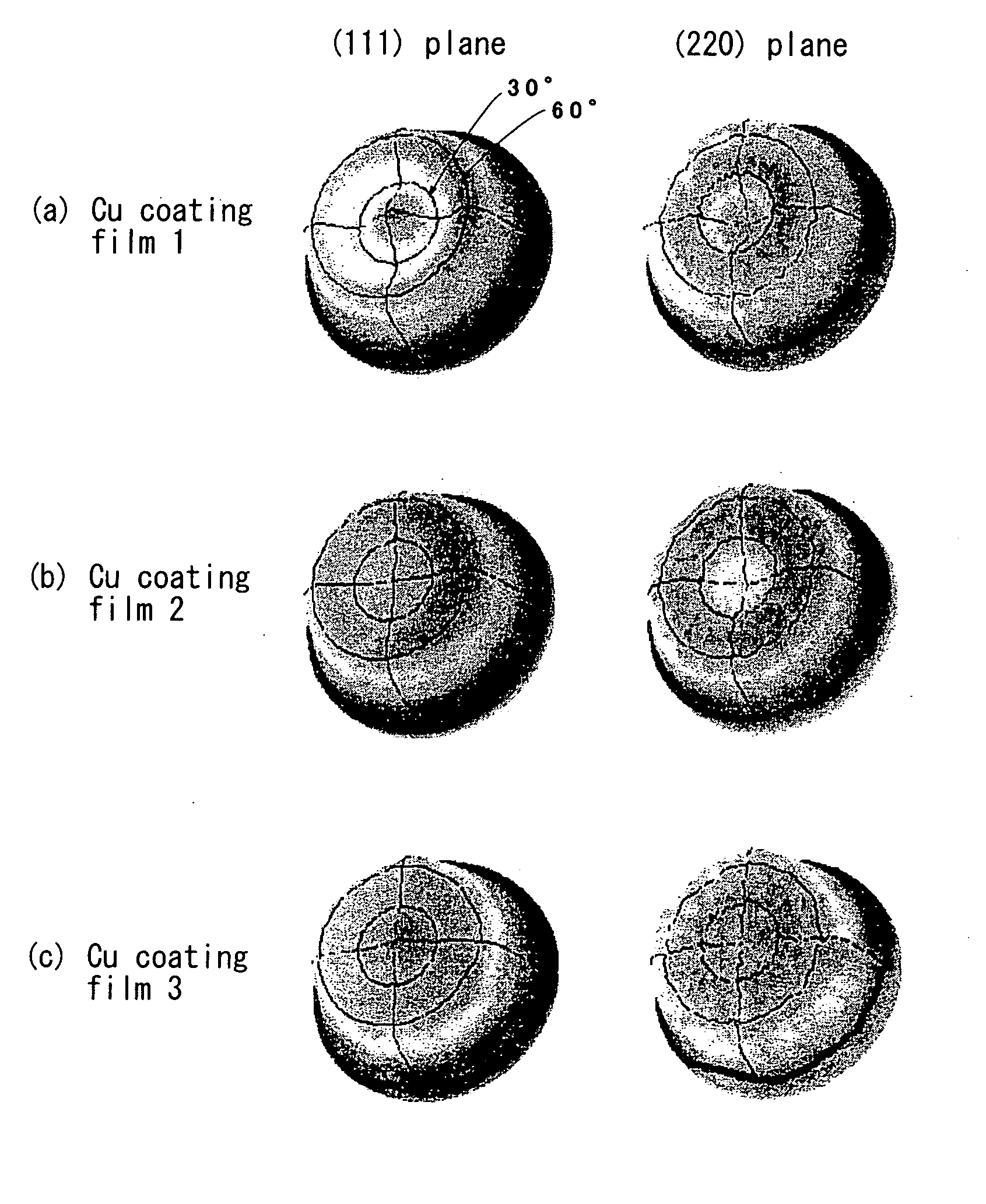
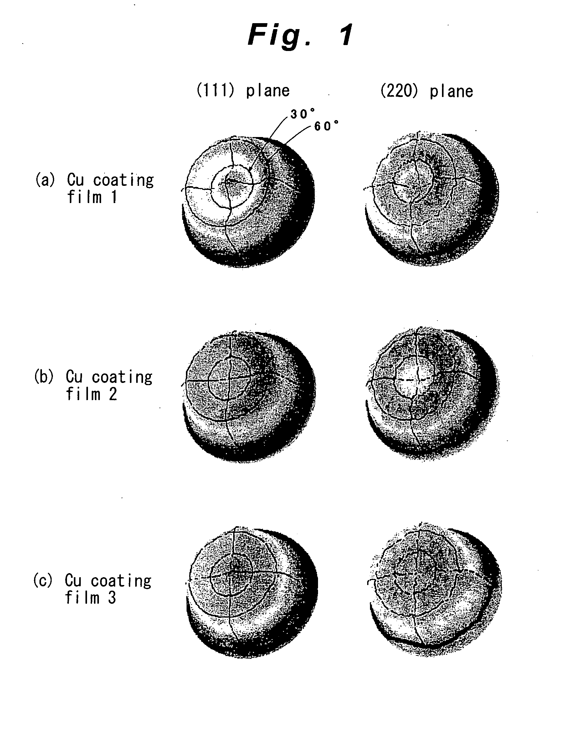
[0033]A nickel (Ni) coating film of 1 μm in thickness was formed on the surface of the magnet test piece by Ni strike plating (Process step 1), and a copper (Cu) coating film of 8 μm in thickness was formed further thereon by Cu pulse plating (Process step 2). Furthermore, in the same plating bath, an application of electric current in pulsed waveform was switched to applying continuous electric current, to thereby form a Cu coating film of 27 μm in thickness on the surface thereof by Cu continuous current-applying electric plating (Process step 3). The plating conditions are as follows.
Process Step 1: Ni Strike Plating
[0034]
Bath compositionNickel sulfate hexahydrate130 g / L (0.49 mol / L)Ammonium chloride15 g / L (0.28 mol / L)Diammonium citrate60 g / L (0.27 mol / L)Boric acid15 g / L (0.24 mol / L)Sodium sulfate35 g / L (0.25 mol / L)Bath temperature50° C.pH6.5 (adjusted with 28% ammonia water)Current density0.3 A / dm2Retention methodRack
Process Step 2: Cu Pulse Plating
[0035]
Bath compositionCopper s...
example 2
[0047]Under the same plating conditions as those of Example 1, a Ni coating film of 1 μm in thickness was formed on the surface of the magnet test piece by Ni strike plating, and a Cu coating film of 8 μm in thickness was formed further thereon by Cu pulse plating. Furthermore, in the same plating bath, an application of electric current in pulsed waveform was switched to applying continuous electric current, to thereby form a Cu coating film of 10 μm in thickness on the surface thereof by Cu continuous current-applying electric plating.
[0048]Thus obtained five magnet test pieces (samples) each having a multilayered metal coating film of 19 μm in total thickness on the surface thereof were subjected to pressurized hydrogen test at 60° C. under 1 MPa, and the time elapsed to disrupt the sample was measured. As a result, no sample disruption occurred even after 2000 hours from the starting of the test.
example 3
[0049]Under the plating conditions below, a Cu coating film of 1 μm in thickness was formed on the surface of the magnet test piece by Cu strike plating (Process step 1), and under the same plating conditions as those of Process steps 2 and 3 of Example 1, a Cu coating film of 8 μm in thickness was formed further thereon by Cu pulse plating. Furthermore, in the same plating bath, an application of electric current in pulsed waveform was switched to applying continuous electric current, to thereby form a Cu coating film of 27 μm in thickness on the surface thereof by Cu continuous current-applying electric plating.
Process Step 1: Cu Strike Plating
[0050]
Bath compositionCopper sulfate pentahydrate0.06 mol / L1-Hydroxyethylidene-1,1-diphosphonic acid0.15 mol / LPotassium pyrophosphate0.2 mol / LBath temperature60° C.pH10 (adjusted with sodium hydroxide)Current density1 A / dm2Retention methodRack
[0051]Thus obtained five magnet test pieces (samples) each having a multilayered metal coating film ...
PUM
| Property | Measurement | Unit |
|---|---|---|
| Dissociation constant | aaaaa | aaaaa |
| Dissociation constant | aaaaa | aaaaa |
| Dissociation constant | aaaaa | aaaaa |
Abstract
Description
Claims
Application Information
 - R&D
- Intellectual Property
- Life Sciences
- Materials
- Tech Scout
- Unparalleled Data Quality
- Higher Quality Content
- 60% Fewer Hallucinations
Browse by: Latest US Patents, China's latest patents, Technical Efficacy Thesaurus, Application Domain, Technology Topic, Popular Technical Reports.
© 2025 PatSnap. All rights reserved.Legal|Privacy policy|Modern Slavery Act Transparency Statement|Sitemap|About US| Contact US: help@patsnap.com