Carbon Heat-Treatment Process

a heat treatment process and carbon technology, applied in the field of activated carbon thermal production, can solve the problems of temperature spike and product quality reduction, and achieve the effects of reducing capital cost requirements, easy adjustment, and precise repeatability

Active Publication Date: 2011-01-06
PNEUMATIC PROCESSING TECH
View PDF62 Cites 6 Cited by
  • Summary
  • Abstract
  • Description
  • Claims
  • Application Information

AI Technical Summary

Benefits of technology

[0035]15. Additionally, another unique method of AC halogenation can be utilized when flash activated AC has been produced concurrently or simultaneously with an industrial mineral such as calcium oxide as previously described or has been pre-mixed with a metallic mineral, oxide or salt or a combination of two or more of these compounds. This method reacts the co-product AC with a halide acid resulting in a halogenated product consisting of halide salt(s) (i.e. Calcium bromide, iron bromides). Some halide ...

Problems solved by technology

In most cases the finer feed will experience excessive activation or gasification resulting in product loss while the more granular feed will experience a lesser degree...

Method used


Image

  • Carbon Heat-Treatment Process
  • Carbon Heat-Treatment Process
  • Carbon Heat-Treatment Process

Examples


Embodiment Construction

ul>

[0036]Overall there is a need for a process that can significantly reduce the capital cost requirements for AC production and processing and that is inherently stable, easily adjustable, and precisely repeatable.

[0037]Additional features and advantages of the invention will be forthcoming from the following detailed description of certain preferred embodiments when read in conjunction with the accompanying drawings.

BRIEF DESCRIPTION OF THE DRAWINGS

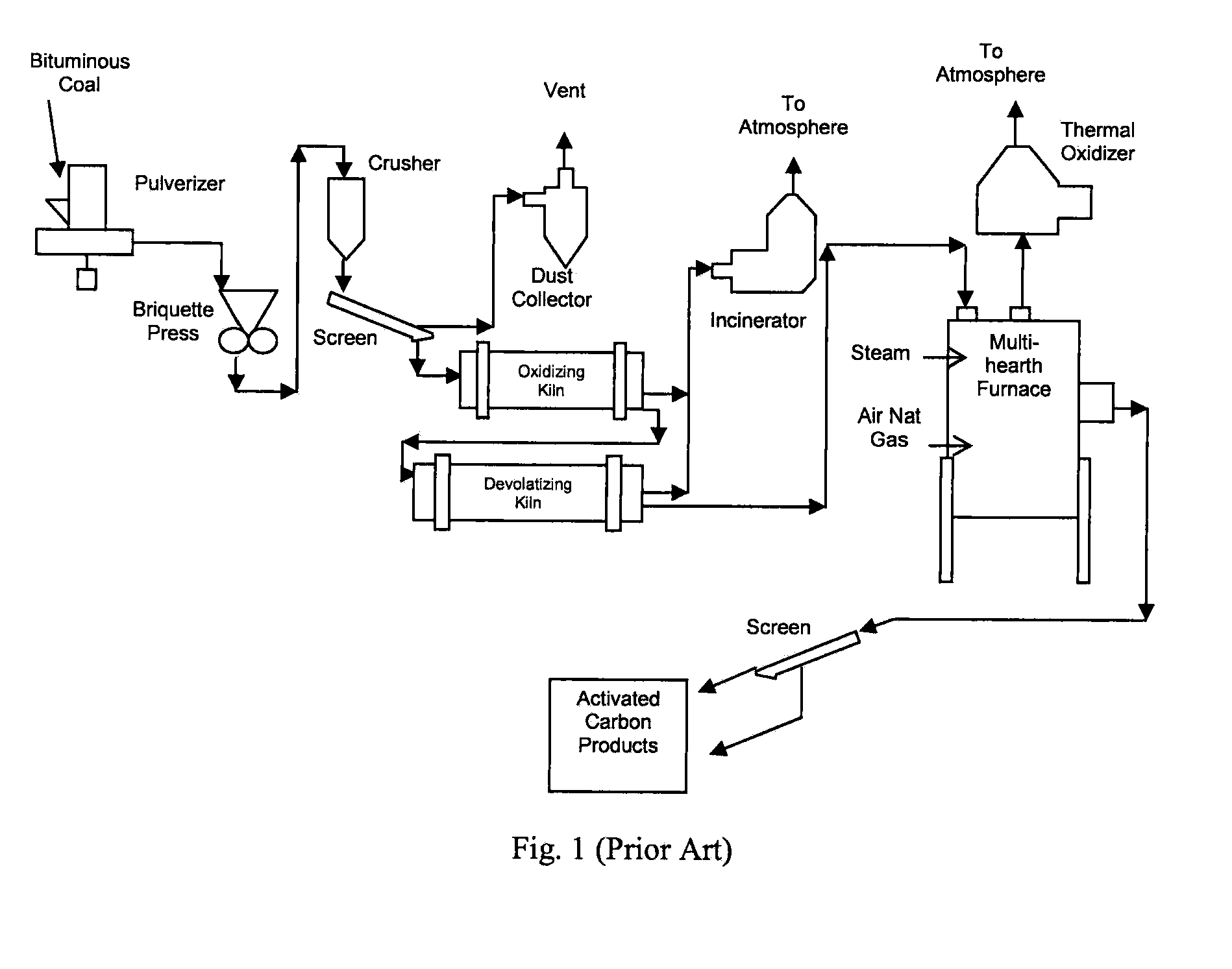
[0038]FIG. 1 schematically illustrates an activation system (for example, a calcining plant) of the prior art.

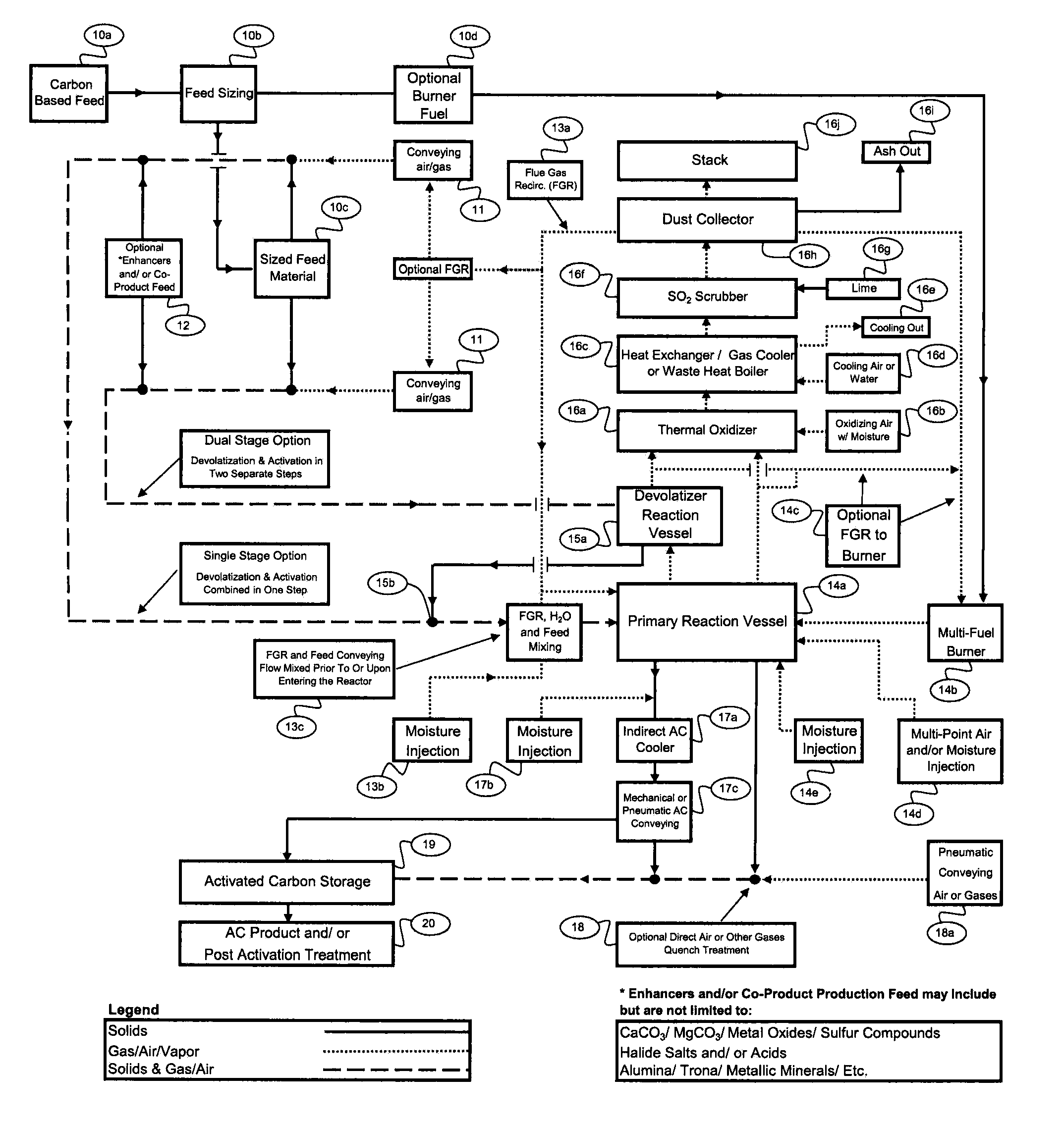
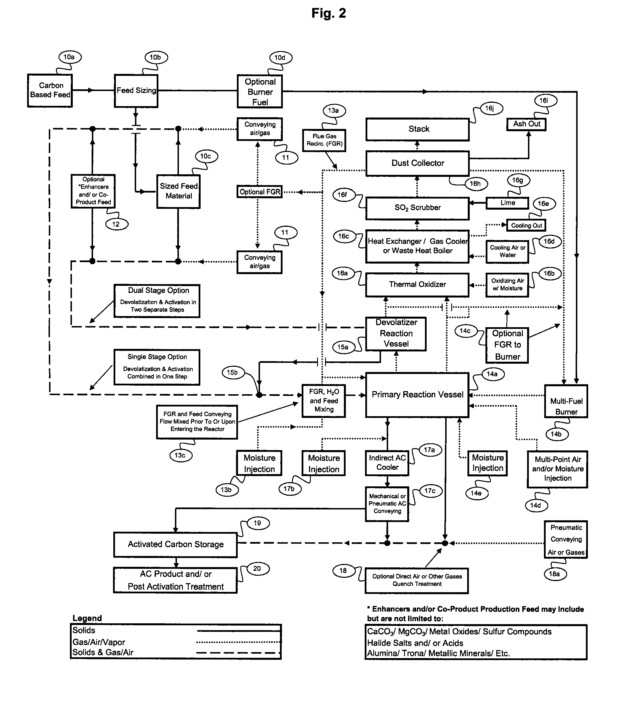
[0039]FIG. 2 illustrates an overview flow diagram of a system and methods according to the invention.

[0040]FIG. 3 illustrates a flow diagram of a single-stage method according to the invention.

[0041]FIG. 4 illustrates a flow diagram of a dual-stage method according to the invention.

DESCRIPTION OF THE PREFERRED EMBODIMENTS

[0042]Processes according to the invention can be divided into the following main categories: 1) Carbonaceous...


PUM


Abstract

Methods for producing devolatilized and/or activated carbon in a reactor or reaction vessel of a heat treatment system from a suitable carbonaceous feedstock by introducing the feedstock into the reactor tangentially at a rotational velocity of at least 90 RPM. The methods include the steps of providing a combination of conveying means and a gas flow having various compositions and creating distinct carbonaceous feedstock material flow patterns and process conditions such that the feedstock is conveyed through the reactor or reaction vessel and heated via combustion, thereby producing activated carbon or other heat-treated carbons while concurrently avoiding adverse reaction conditions. Single and two-stage heat treatment systems may be used to heat a carbon feedstock, to which one or more industrial minerals may be added to co-produce compositions such as lime with the heat-treated carbon.

Description

BACKGROUND OF THE INVENTION[0001]1. Field of the Invention[0002]The invention relates to the thermal production of activated carbon and other heat-treated carbons.[0003]2. Description of the Related Art[0004]Recent environmental awareness has focused on the need to remove harmful mercury emissions from coal fired power plants. These efforts have led to several developments with regards to effective mercury removal techniques. The most successful method for mercury removal utilizes pulverized activated carbon injected into the flue gas stream of a coal fired power plant. Extensive research in this field has demonstrated that not all activated carbons effectively remove mercury. There are many factors that influence mercury removal effectiveness using activated carbon in coal fired power plants such as coal fuel type, mercury concentrations, etc. One of the largest factors in the ability of activated carbon to adsorb mercury is the activated carbon pore structure. Not all activated ca...

Claims


Application Information

Patent Timeline
IPC IPC(8): C09C1/44C01B32/336
CPCC01B31/08C01B32/30C01B32/312
Inventor JONES, MICHAEL A.
Owner PNEUMATIC PROCESSING TECH
Why Eureka
Try Eureka