
Semiconductor memory device using hot electron injection

a memory device and semiconductor technology, applied in semiconductor devices, solid-state devices, instruments, etc., can solve the problems of unsolved degraded programming characteristics and inability to redu

Inactive Publication Date: 2010-09-30
LAPIS SEMICON CO LTD
View PDF0 Cites 3 Cited by
  • Summary
  • Abstract
  • Description
  • Claims
  • Application Information

AI Technical Summary

Benefits of technology

[0009]An object of the present invention is to provide a semiconductor memory device in which degradation of programming characteristics of memory cell transistors is prevented without degrading the characteristics of peripheral circuits.
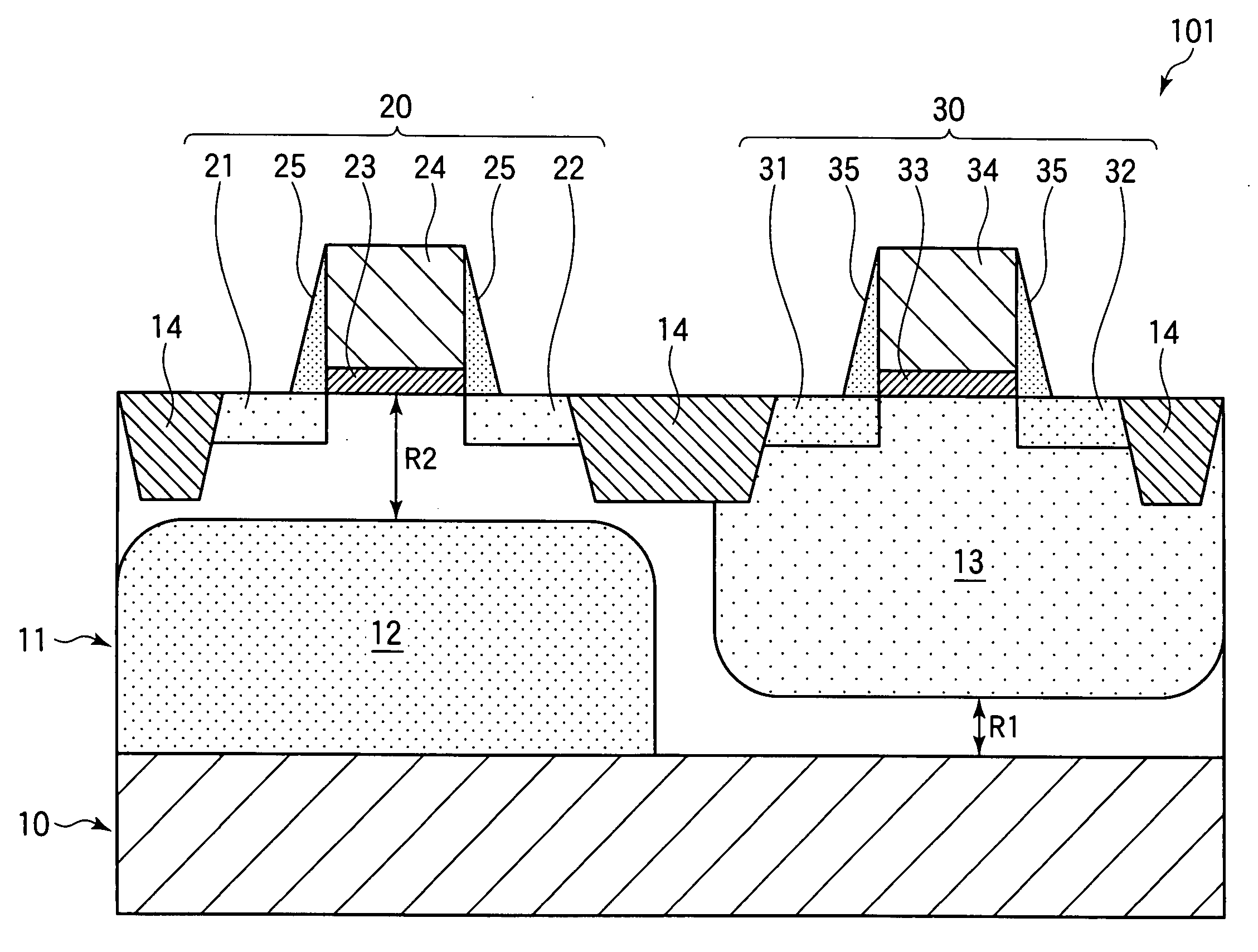
[0014]During programming by hot electron injection, substrate current flows from the part of the semiconductor layer near the source and drain regions of the memory cell transistor through the diffusion region into the semiconductor substrate. In passing through the diffusion region, the substrate current experiences less voltage drop than it would experience if forced to flow through other parts of the semiconductor layer. The reduced voltage drop means a reduced shift in the potential of the semiconductor layer near the source and drain regions of the memory cell transistor. If the diffusion region has a sufficiently low resistivity and is sufficiently close to the memory cell transistor, adverse effects of the substrate current on the hot electron injection process can be avoided.

Problems solved by technology

Accordingly, it has not been possible to reduce the thickness of the p−-type semiconductor layer below the memory cell transistors sufficiently to eliminate the rise in the substrate potential in the vicinity of their source and drain regions, and the problem of degraded programming characteristics remains unsolved.

Method used


Image

  • Semiconductor memory device using hot electron injection
  • Semiconductor memory device using hot electron injection
  • Semiconductor memory device using hot electron injection

Examples


Embodiment Construction

[0020]An embodiment of the invention will now be described with reference to the attached drawings, in which like elements are indicated by like reference characters.

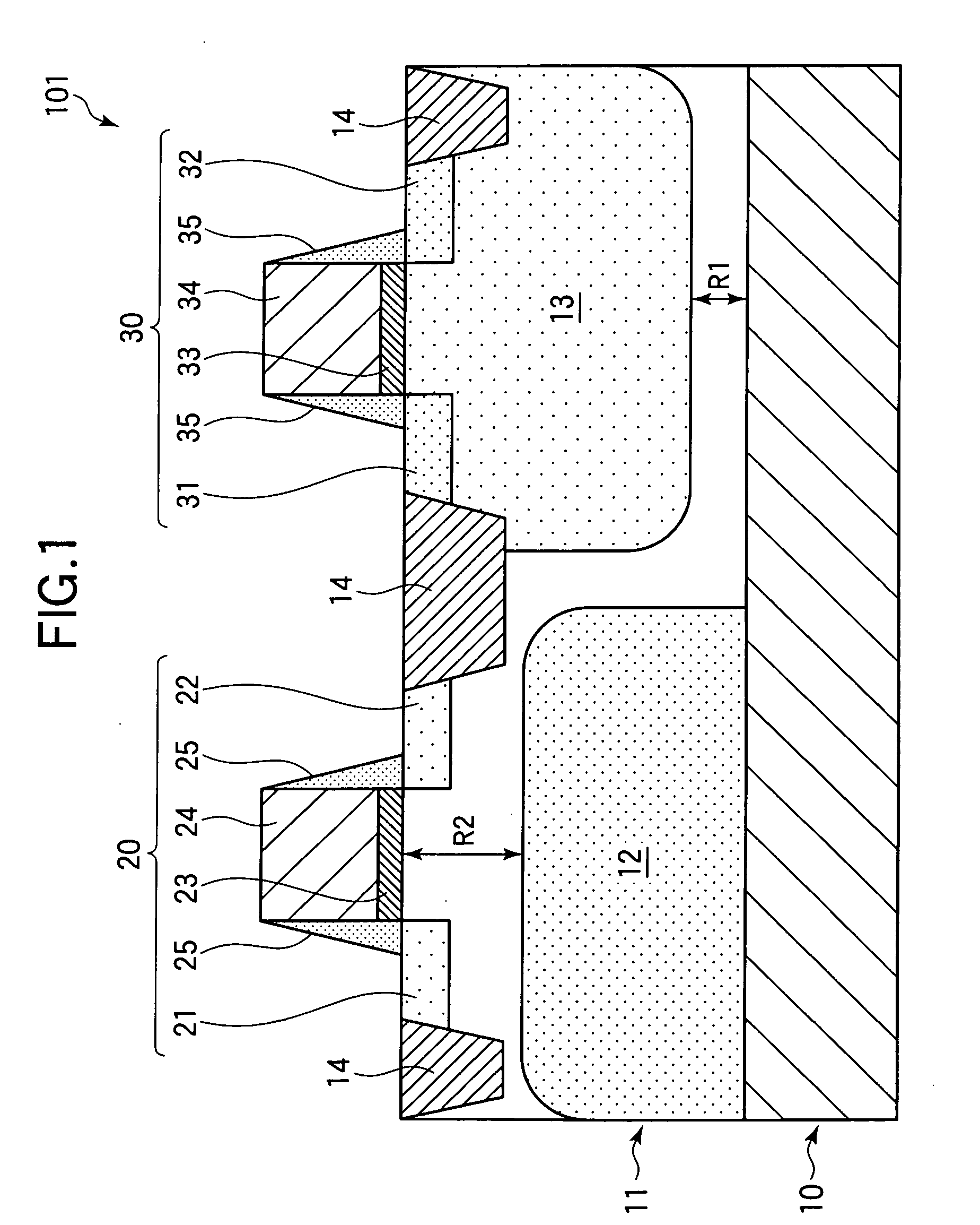
[0021]Referring to FIG. 1, the embodiment is a semiconductor memory device 101 including a memory cell transistor 20 and a peripheral circuit transistor 30. Although the semiconductor memory device 101 includes an array of memory cell transistors 20, only a single memory cell transistor is shown for simplicity. The peripheral circuits of the semiconductor memory device 101 include a plurality of both p-channel metal-oxide-semiconductor (PMOS) transistors and n-channel metal-oxide-semiconductor (NMOS) transistors, which are used for reading and programming data in the memory cells, but only a single PMOS transistor is shown for simplicity. Other necessary structures, such as interlayer dielectric films, contact holes, metal interconnections, and a passivation layer are omitted from FIG. 1 as they are well known.

[0022]The...


PUM


Abstract

A semiconductor memory device has a low-resistivity semiconductor substrate on which a higher-resistivity semiconductor layer of the same conductivity type is formed. Memory cell transistors are formed in the semiconductor layer. A diffusion region, also of the same conductivity type, is formed below the memory cell transistors. The resistivity of the diffusion region is lower than the resistivity of the semiconductor layer. In the programming of data into the memory cell transistors by hot electron injection, the diffusion region reduces the voltage drop due to current flow from the part of the semiconductor layer near the memory cell transistors into the semiconductor substrate, thereby reducing unwanted elevation of the potential of the semiconductor layer.

Description

BACKGROUND OF THE INVENTION[0001]1. Field of the Invention[0002]The present invention relates to a semiconductor memory device, more particularly to a semiconductor memory device in which data are programmed by hot electron injection.[0003]2. Description of the Related Art[0004]A semiconductor memory device in which data are programmed by hot electron injection usually has memory cell transistors formed in a p−-type substrate, that is, a substrate made of a comparatively lightly doped p-type semiconductor material. To program data into a memory cell transistor, high gate and drain voltages are applied to the transistor and hot electrons generated by the high electric field between the source and drain regions are drawn to the gate electrode by the electric field between the gate electrode and the drain region. The programming operation also generates holes that flow through the semiconductor substrate as a substrate current due to the electric field between the drain region and the ...

Claims


Application Information

Patent Timeline
IPC IPC(8): H01L27/088
CPCG11C16/0425G11C16/10H01L29/7885H01L27/11526H01L27/11531H01L27/11521H10B41/42H10B41/40H10B41/30
Inventor SAEKI, KATSUTOSHI
Owner LAPIS SEMICON CO LTD
Learn More