
Method for the plasma cleaning of the surface of a material coated with an organic substance and the installation for carrying out said method

a technology of organic substances and plasma cleaning, which is applied in the direction of plasma techniques, electric discharge tubes, chemistry apparatus and processes, etc., can solve the problems of complex ancillary workshops, low oxygen content in the mixture, and inability to treat strips at speeds exceeding 10 m/min for lack of power

Inactive Publication Date: 2010-06-10
USINOR SA
View PDF12 Cites 8 Cited by
  • Summary
  • Abstract
  • Description
  • Claims
  • Application Information

AI Technical Summary

Benefits of technology

The process achieves uniform and rapid cleaning of metal strips at high speeds with reduced energy consumption and minimal polymerization, maintaining the mechanical properties of the steel while effectively removing organic coatings, as demonstrated by increased oxygen radical density and efficient degreasing results.

Problems solved by technology

For environmental reasons, this process requires the installation of complex ancillary workshops for the reprocessing of eco-toxic co-products.
Other technical solutions are used to prevent the formation of such co-products, such as for example laser ablation, which has the effect of desorbing the organic compounds photochemically, but does not allow strips to be treated at speeds exceeding 10 m / min for lack of power.
The proportion of oxygen in the mixture is therefore low, and it is found that the treatment is not sufficiently rapid, probably because of the low density of reactive oxygenated species, but also because of inopportune polymerization of the organic substance to be removed.
The use of helium as plasma gas and the complexity of the equipment makes this process as expensive and as difficult to implement as a conventional vacuum process.
Furthermore, it does not allow degreasing of a strip running at a speed of greater than 3 m / min.
In addition to complex equipment, working at these pressure in air requires the discharge striking voltage, which is directly proportional to the pressure, to be considerably increased.

Method used


Image

  • Method for the plasma cleaning of the surface of a material coated with an organic substance and the installation for carrying out said method
  • Method for the plasma cleaning of the surface of a material coated with an organic substance and the installation for carrying out said method
  • Method for the plasma cleaning of the surface of a material coated with an organic substance and the installation for carrying out said method

Examples


example 1

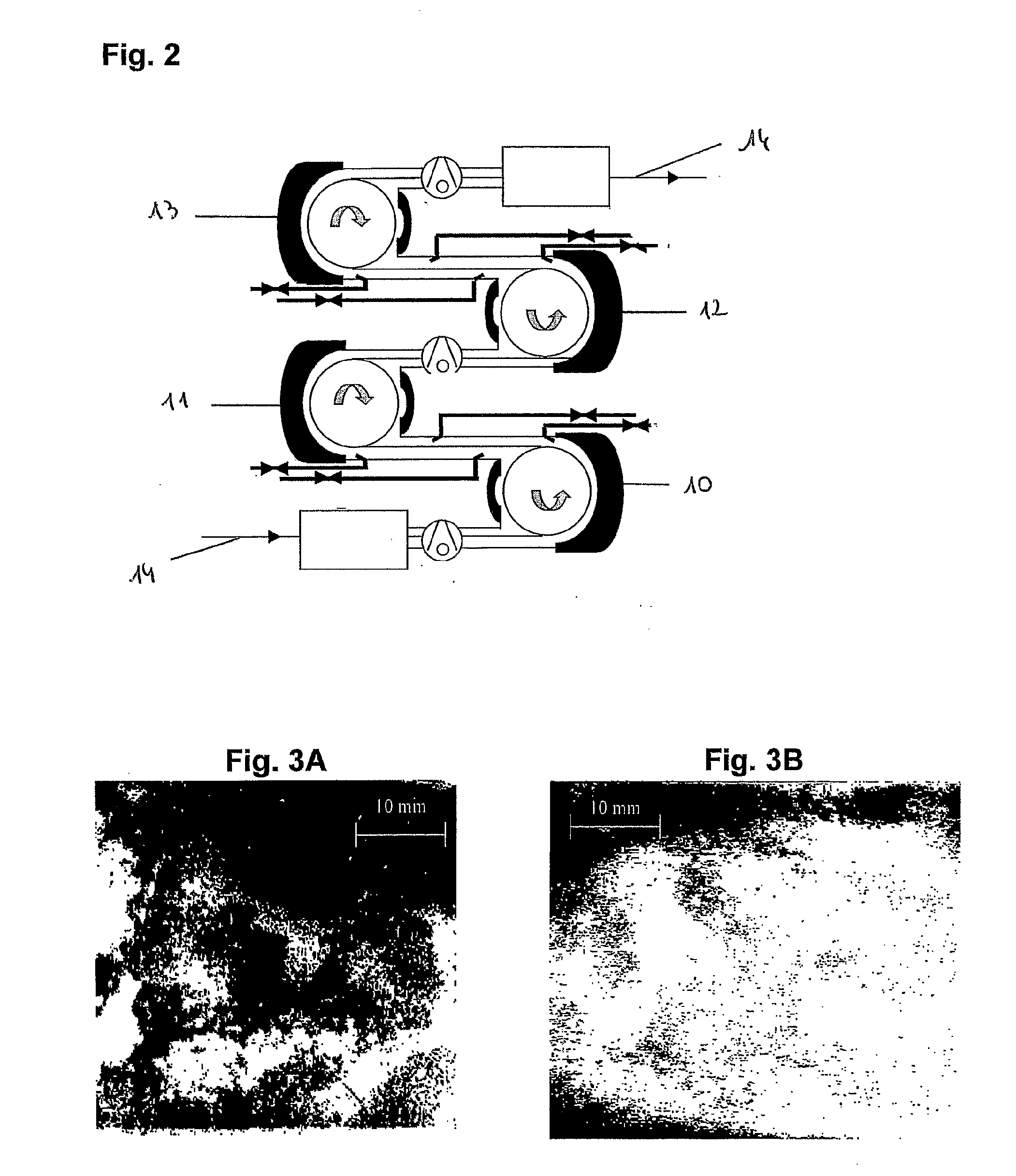
[0047]Two identical carbon steel strips, coated with a 186 mg / m2 protective oil layer were treated. The other parameters were identical for the two treatments, namely:[0048]200 mbar of oxygen;[0049]12 kHz sinusoidal voltage; 3.6 kV; current: 30 mA;[0050]inter-electrode distance: 5 mm.

[0051]The strip treatments illustrated in FIGS. 3A and 3B differ only by UV radiation being imposed in one case and not in the other.

[0052]FIG. 3 shows images of the surface of strips treated by a discharge initiated in just oxygen, with (FIG. 3B) and without (FIG. 3A) additional UV (253 nm) irradiation. The dark areas correspond to the non-greased regions where the oil has polymerized.

[0053]It may be seen that applying UV radiation in addition to the discharge results in less polymerization of the oil, thus allowing better cleaning, in a shorter time.

[0054]Applying UV radiation whose wavelength corresponds to the dissociative absorption of ozone results in the uniform presence of oxygen radicals on the...

example 2

[0062]FIG. 5 shows, using optical emission spectroscopy, that the density of active oxygenated species O. varies linearly with the intensity of the current applied in the discharge.

[0063]The discharge currents plotted in this figure were varied both at constant voltage, by varying the rate of application of the V, and therefore varying the impedance of the dielectric, and at constant frequency by varying the voltage. This FIG. 5 therefore shows that the density of active species depends only on the intensity of the discharge current and is not in any way influenced by the discharge voltage at constant current. This means that it is possible to obtain the same density of active species at power levels that differ only by the imposed voltage, the current remaining constant. However, it has been found that too high a voltage results in polymerization of the oil, which tends to inhibit the rate of oxidation of the organic residues present on the surface of the strip. In addition, indust...

example 3

[0066]A 20 cm2 strip covered with 186 mg / m2 of protective oil was treated by the process according to the invention. In the present case, the discharge was initiated in a stream of oxygen at a pressure of 350 mbar. The oxygen and / or ozone molecules formed from the recombined free radicals O. were not re-dissociated. FIG. 6 shows the change in coating weight of protective oil present on the strip as a function of the electron dose It / S (i.e. the electron current density multiplied by the treatment time). Application of the stream allows uniform treatment of the strip, which was confirmed by grazing-incidence infrared absorption spectroscopy (IRRAS).

[0067]FIG. 7 shows the Auger electron spectrum of the surface of the strip degreased using a discharge involving an electron dose of 21 mC / cm2. Only the iron and oxygen peaks are present. The absence of a carbon peak around 273 eV confirms that the strip was completely degreased.


PUM

PropertyMeasurementUnit
pressureaaaaaaaaaa
pressureaaaaaaaaaa
frequenciesaaaaaaaaaa

Abstract

The invention relates to a method of cleaning the surface of a material that is coated with an organic substance. The inventive method is characterized in that it comprises the following steps, consisting in: introducing the material into a treatment chamber, having a pressure of between 10 mbar and 1 bar therein, which is supplied with a gas stream containing at least 90 volume percent of oxygen; and generating a plasma by passing an electric discharge between the surface of the material and a dielectric-covered electrode in order to break down the organic substance under the action of the free radicals O thus produces. The invention also relates to an installation that is used to carry out said method.

Description

BACKGROUND OF THE INVENTION[0001]The present invention relates to a process for cleaning, by means of a plasma at a pressure between 10 mbar and 1 bar, the surface of a material coated with an organic substance, and to an installation for implementing this process, more particularly one intended for cleaning metal strip.[0002]Within the context of the present application, the expression “organic substance” is understood to mean any water-insoluble compound containing carbon, oxygen and hydrogen.DESCRIPTION OF THE PRIOR ART[0003]Strip coming from the various manufacturing lines are generally covered with an oil film which may have come from two sources. Firstly, this film may have been applied by spraying protective oil, so as to protect the surface of the strip from corrosion. However, it may also derive from a residual oil film in the case of strip coming from a cold rolling mill or skin-pass. In both cases, the oil coating weights may be up to several hundred mg per m2.[0004]To de...

Claims


Application Information

Patent Timeline
Patent Type & Authority Applications(United States)
IPC IPC(8): B08B13/00C23F1/08B08B7/00H05H1/24C23G5/00
CPCB08B7/0035H01J37/32348C23G5/00B08B7/00H01J37/32
Inventor SILBERBERG, ERICMICHEL, ERICRENIERS, FRANCOISBUESS-HERMAN, CLAUDINE
Owner USINOR SA
Learn More