Method of manufacturing catalyst material
a technology of catalyst material and catalyst material, which is applied in the direction of physical/chemical process catalyst, separation process, filtration separation, etc., can solve the problems of reducing fuel efficiency, difficult to burn carbon at a low temperature, and soot discharged from engines such as diesel engines or the lik
- Summary
- Abstract
- Description
- Claims
- Application Information
AI Technical Summary
Benefits of technology
Problems solved by technology
Method used
Image
Examples
example 1
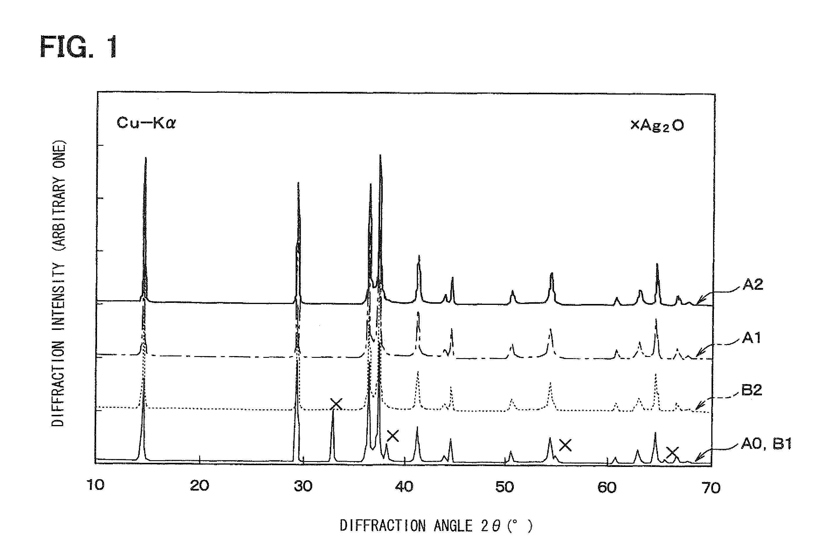
[0064]In the present example, a delafossite-type AgAlO2 is manufactured as the catalyst material and the catalyst characteristics thereof are evaluated. A manufacturing method of the catalyst material in the present example is the above-mentioned first hydrothermal synthesis method which involves base material synthesis, hydrothermal synthesis, water washing, ammonia washing, second water washing, and drying.
[0065]First, in the base material synthesis, a uniform mixture of an alkali salt (for example, sodium nitrate or the like) and an aluminum salt (for example, aluminum nitrate) are thermally decomposed at a temperature of 800 to 1000° C., thereby synthesizing sodium aluminate (NaAlO2) serving as the base material.
[0066]Then, the base material synthesized and silver oxide (Ag2O) are encapsulated into a pressure vessel and subjected to the hydrothermal treatment at a temperature of 150 to 180° C., thereby obtaining the delafossite-type AgAlO2 containing the Ag compound. The thus-ob...
example 2
[0084]In the present example, a ceramic honeycomb structure supporting the catalyst material (specimen A1) manufactured in Example 1 is manufactured.
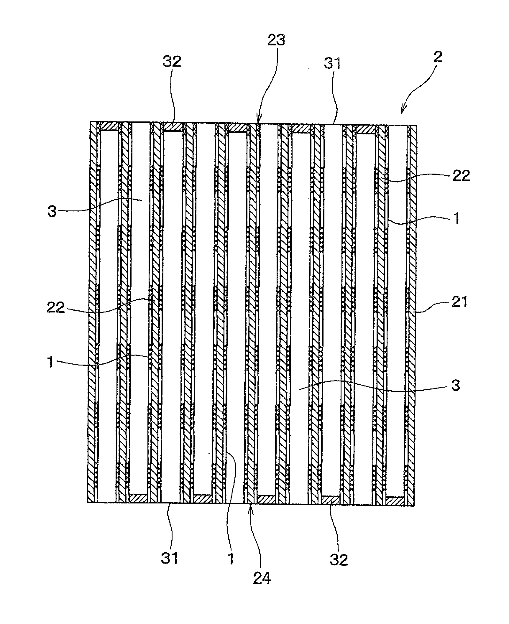
[0085]FIG. 3 is a perspective view of the ceramic honeycomb structure 2 of Example 2, FIG. 4 is a sectional view of the ceramic honeycomb structure 2 of Example 2 in the longitudinal direction, and FIG. 5 shows a state in which exhaust gas 10 passes through the ceramic honeycomb structure 2 of Example 2.
[0086]As shown in FIGS. 3 to 5, the ceramic honeycomb structure 2 of the present example includes an outer peripheral wall 21, partition walls 22 provided in the form of honeycomb inside the outer peripheral wall 21, and a plurality of cells 3 partitioned by the partition walls 22.
[0087]The cell 3 is partly opened at both ends 23 and 24 of the ceramic honeycomb structure 2. That is, parts of cells 3 are opened to both ends 23 and 24 of the honeycomb structure 2, and the remaining cells 3 are closed by stoppers 32 formed on the both ends ...
example 3
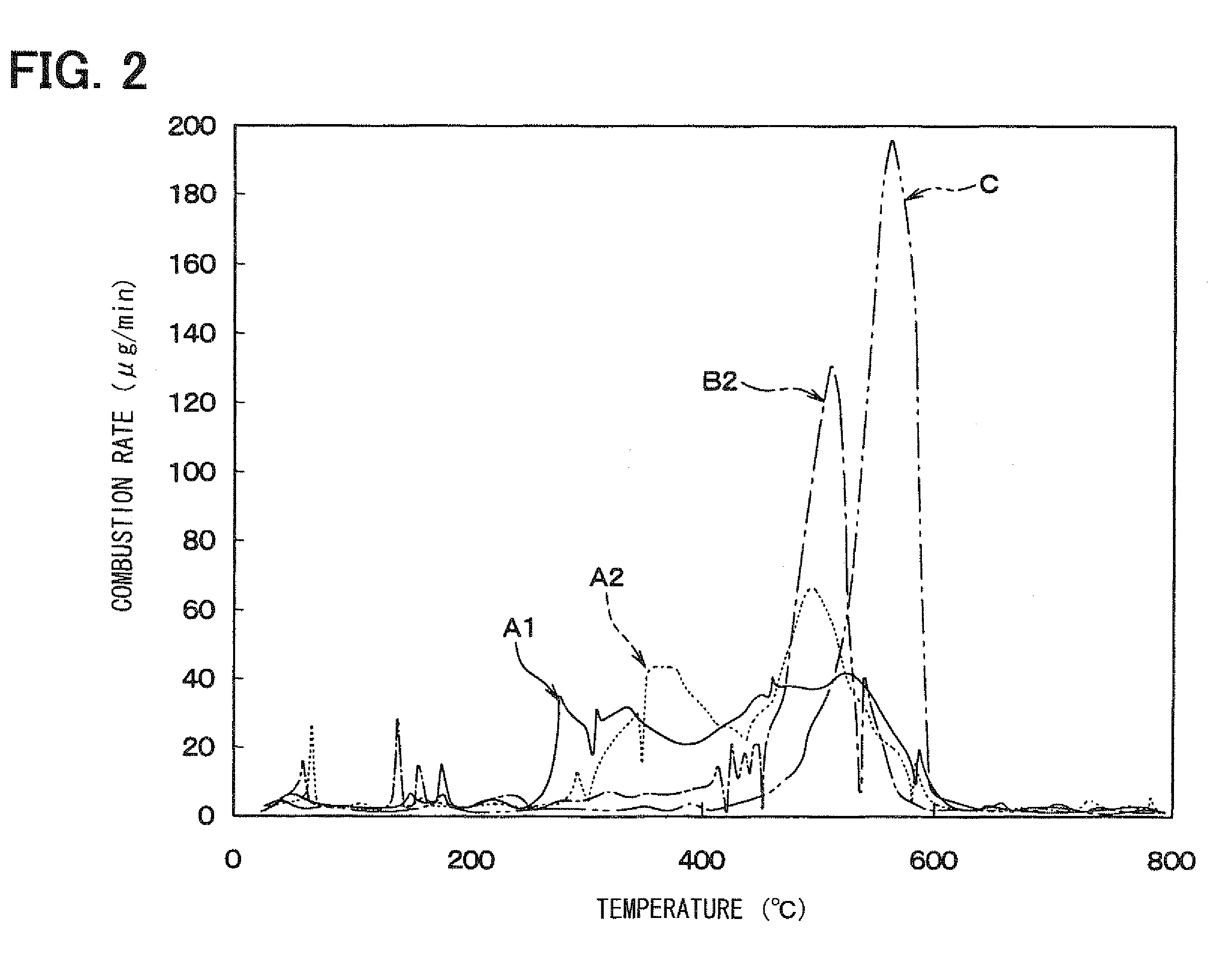
[0105]In Example 3, the combustion temperature of delafossite-type CuAlO2 was compared with that of the specimen A1 which was the delafossite-type AgAlO2 manufactured in Example 1. The comparison among both specimens was performed by measuring the heat balance and change in weight of carbon fines in heating each catalyst material together with the carbon fines by use of a differential thermogravimetric simultaneous measurement device in the same way as that shown in FIG. 2.
[0106]FIG. 12 is a diagram showing a relationship between the change in weight and heating temperature of the delafossite-type AgAlO2 (specimen A1) and the delaffosite type CuAlO2. The delaffosite type CuAlO2 was manufactured by burning a mixture of copper oxide and aluminum nitrate at a temperature of 1100° C. for four hours. As can be seen from FIG. 12, it is found that the delafossite-type CuAlO2 does not have low-temperature combustion characteristics over a wide range of low temperature, unlike Example 1.
[010...
PUM
| Property | Measurement | Unit |
|---|---|---|
| temperature | aaaaa | aaaaa |
| temperature | aaaaa | aaaaa |
| thickness | aaaaa | aaaaa |
Abstract
Description
Claims
Application Information
 - R&D
- Intellectual Property
- Life Sciences
- Materials
- Tech Scout
- Unparalleled Data Quality
- Higher Quality Content
- 60% Fewer Hallucinations
Browse by: Latest US Patents, China's latest patents, Technical Efficacy Thesaurus, Application Domain, Technology Topic, Popular Technical Reports.
© 2025 PatSnap. All rights reserved.Legal|Privacy policy|Modern Slavery Act Transparency Statement|Sitemap|About US| Contact US: help@patsnap.com


