
Method of preparing lithographic printing plate

a lithographic printing and printing plate technology, applied in the field of preparing lithographic printing plates, can solve the problems of small amount of waste, large space required by automatic developing machines per se, environmental problems, etc., and achieve the effects of small occurrence of development scum, good developing property, and excellent processing property

Inactive Publication Date: 2010-03-11
FUJIFILM CORP
View PDF6 Cites 6 Cited by
  • Summary
  • Abstract
  • Description
  • Claims
  • Application Information

AI Technical Summary

Benefits of technology

[0165]According to the invention, by adjusting a ratio of the polymerizable monomer and the binder polymer in the photosensitive layer of the lithographic printing plate precursor, the effects of the invention are further achieved. Specifically, a weight ratio of polymerizable monomer / binder polymer in the photosensitive layer is preferably 1.2 or more, more preferably from 1.25 to 4.5, most preferably from 2 to 4. Thus, permeability of the developer into the photosensitive layer further increases and the developing property is more improved.
[0166]In the invention, in order to incorporate the above-described constituting components of the photosensitive layer and other constituting components described hereinafter into the photosensitive layer, a part or whole of the constituting components is encapsulated into microcapsules and added to the photosensitive layer as described, for example, in JP-A-2001-277740 and JP-A-2001-277742. In such a case, each constituting component may be present inside or outside the microcapsule in an appropriate ratio.
[0167]As a method of microencapsulating the constituting components of the photosensitive layer, known methods can be used. Methods for the production of microcapsules include, for example, a method of utilizing coacervation described in U.S. Pat. Nos. 2,800,457 and 2,800,458, a method of using interfacial polymerization described in U.S. Pat. No. 3,287,154, JP-B-38-19574 and JP-B-42-446, a method of using deposition of polymer described in U.S. Pat. Nos. 3,418,250 and 3,660,304, a method of using an isocyanate polyol wall material described in U.S. Pat. No. 3,796,669, a method of using an isocyanate wall material described in U.S. Pat. No. 3,914,511, a method of using a urea-formaldehyde-type or urea-formaldehyde-resorcinol-type wall-forming material described in U.S. Pat. Nos. 4,001,140, 4,087,376 and 4,089,802, a method of using a wall material, for example, a melamine-formaldehyde resin or hydroxycellulose described in U.S. Pat. No. 4,025,445, an in-situ method by polymerization of monomer described in JP-B-36-9163 and JP-B-51-9079, a spray drying method described in British Patent 930,422 and U.S. Pat. No. 3,111,407, and an electrolytic dispersion cooling method described in British Patents 952,807 and 967,074, but the invention should not be construed as being limited thereto.
[0168]A preferable microcapsule wall used in the invention has three-dimensional crosslinking and has a solvent-swellable property. From this point of view, a preferable wall material of the microcapsule includes polyurea, polyurethane, polyester, polycarbonate, polyamide and a mixture thereof, and particularly polyurea and polyurethane are preferred. Further, a compound having a crosslinkable functional group, for example, an ethylenically unsaturated bond, capable of being introduced into the binder polymer described above may be introduced into the microcapsule wall.
[0169]The average particle size of the microcapsule is preferably from 0.01 to 3.0 μm, more preferably from 0.05 to 2.0 μm, and particularly preferably from 0.10 to 1.0 μm. In the above-described range, preferable resolution and good time-lapse stability can be achieved.<Other Constituting Components of Photosensitive Layer>
[0170]Into the photosensitive layer according to the invention, various additives can further be incorporated, if desired. Such additives are described in detail below.<Surfactant>

Problems solved by technology

However, in view of the environment and safety, a processing with a developer closer to a neutral range and a small amount of waste liquid are problems to be solved.
However, since hitherto known development processing comprises three steps of developing with an aqueous alkali solution having pH of 11 or more, washing of the alkali agent with a water-washing bath and then treating with a gum solution mainly comprising a hydrophilic resin as described above, an automatic developing machine per se requires a large space and problems of the environment and running cost, for example, disposal of the development waste liquid, water-washing waste liquid and gum waste liquid still remain.
However, since the developing method is required a water-washing step and a treatment step with a gum solution, it does not resolve the problems of the environment and running cost.
However, since the printing plate obtained by the processing is left in the state that the alkali of pH 12 adheres on the surface thereof, a problem in view of safety of an operator arises and with the lapse of long time after the preparation of printing plate until the initiation of printing, the image area gradually dissolves to result in deterioration in printing durability or ink-receptive property.
Also, a problem arises in that the pH of the developer decreases due to carbon dioxide present in the air during the processing to cause fluctuation in processing performance.
However, since the processing solutions described in JP-T-2007-538279 (corresponding to US2005 / 0266349A1) and JP-A-2008-33088 do not contain a basic component, it is necessary for enabling the development to make a polymer used in the photosensitive layer hydrophilic and thus, a problem occurs in that printing durability severely degrades.

Method used


Image

  • Method of preparing lithographic printing plate
  • Method of preparing lithographic printing plate
  • Method of preparing lithographic printing plate

Examples


examples

[0429]The present invention will be described in more detail with reference to the following examples, but the invention should not be construed as being limited thereto.

example 36

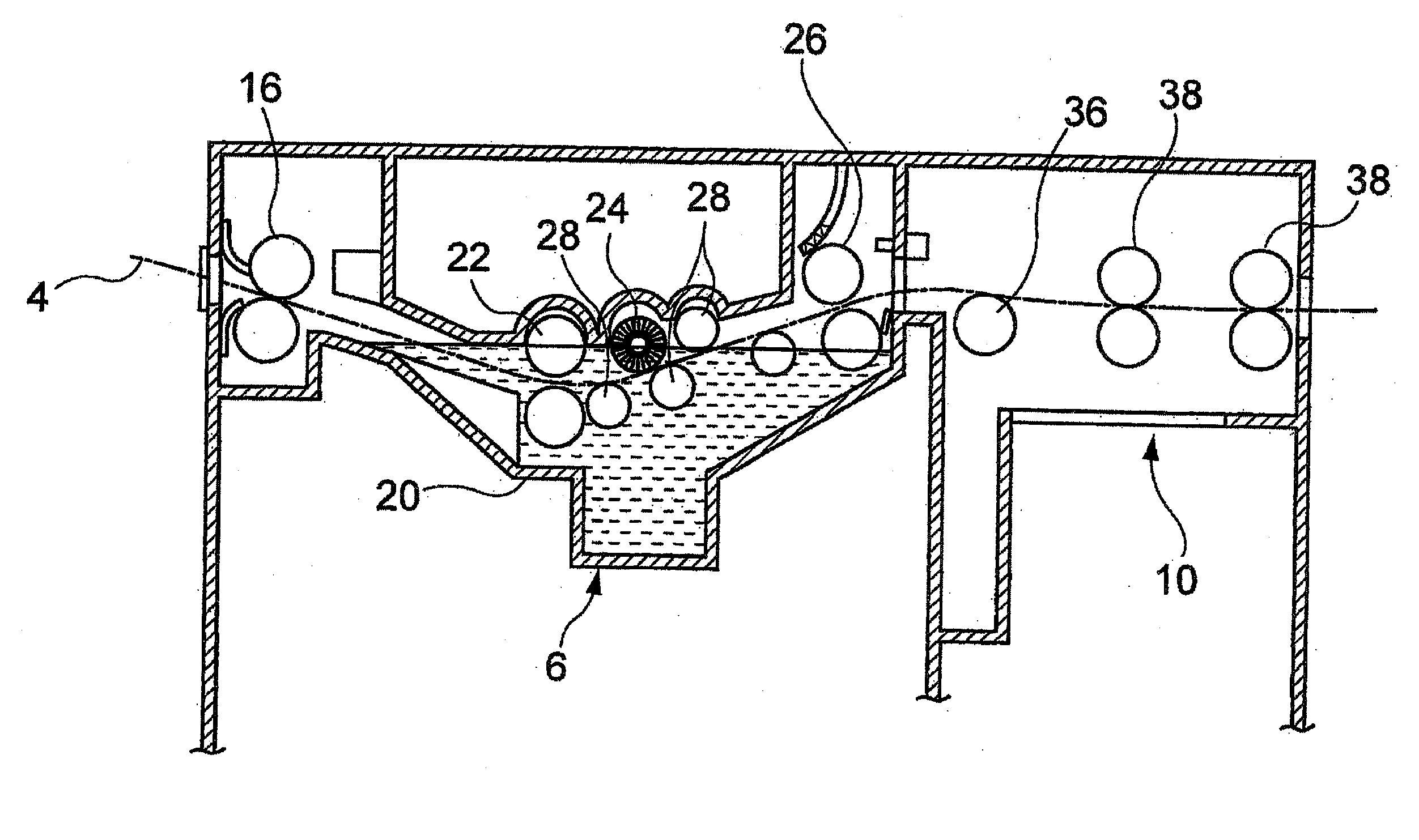
[0460]In the violet semiconductor laser plate setter Vx9600 wherein the InGaN semiconductor laser (emission: 405 nm±10 nm / output: 30 mW) had been replaced with a semiconductor laser having output of 100 mW, the lithographic printing plate precursor of Example 1 was subjected to image exposure in a plate surface exposure amount of 0.25 mJ / cm2. The exposed lithographic printing plate precursor was without performing the pre-heating, subjected to the development processing in the automatic development processor having a structure shown in FIG. 1 using Developer 1. Except as described above, the developing property, printing image-forming property, processing property and printing durability were evaluated in the same manner as in Example 1 and the good evaluation results same as in Example 1 were obtained.

example 37

[0461]The lithographic printing plate precursor of Example 1 was subjected to image exposure in the same manner as in Example 1 and within 30 seconds subjected to the development processing using an automatic development processor (LP1250PLX, produced by Fuji Film Co., Ltd.) having the construction shown in FIG. 2. The automatic development processor was composed of a pre-heating unit, a pre-water washing unit, a developing unit, a water washing unit and a finishing unit in this order. The heating condition in the pre-heating unit was at 100° C. for 10 seconds. To the developing bath, Developer 1 was supplied. To the pre-water washing unit, water washing unit and finishing unit was not supplied any liquid and only their transporting functions were used. Except the development processing described above, the developing property, printing image-forming property, processing property and printing durability were evaluated in the same manner as in Example 1 and the good evaluation result...


PUM

PropertyMeasurementUnit
emission wavelengthaaaaaaaaaa
pHaaaaaaaaaa
pHaaaaaaaaaa

Abstract

A method of preparing a lithographic printing plate includes: exposing imagewise a lithographic printing plate precursor including a hydrophilic support and a photosensitive layer containing a spectral sensitizer, a polymerization initiator, a co-initiator, a polymerizable monomer and a binder polymer with a laser light source having an emission wavelength in a range of from 350 to 450 nm; and removing an unexposed area of the photosensitive layer in the presence of a developer having pH of from 9.1 to 11 and containing a carbonate ion, a hydrogen carbonate ion and at least one of a surfactant and a water-soluble polymer compound, and the co-initiator is a tribromoacetylamide compound.

Description

CROSS-REFERENCE TO RELATED APPLICATIONS[0001]This application claims the benefit of Japanese Patent Application JP 2008-222599, filed Aug. 29, 2008, the entire content of which is hereby incorporated by reference, the same as if set forth at length.FIELD OF THE INVENTION[0002]The present invention relates to a method of preparing a lithographic printing plate.BACKGROUND OF THE INVENTION[0003]In general, a lithographic printing plate is composed of an oleophilic image area accepting ink and a hydrophilic non-image area accepting dampening water in the process of printing. Lithographic printing is a printing method which comprises rendering the oleophilic image area of the lithographic printing plate to an ink-receptive area and the hydrophilic non-image area thereof to a dampening water-receptive area (ink unreceptive area), thereby making a difference in adherence of ink on the surface of the lithographic printing plate, and depositing the ink only on the image area by utilizing the...

Claims


Application Information

Patent Timeline
Patent Type & Authority Applications(United States)
IPC IPC(8): G03F7/20
CPCG03F7/027G03F7/029G03F7/031G03F7/322G03F7/092G03F7/11G03F7/033G03F7/0388
Inventor INNO, TOSHIFUMI
Owner FUJIFILM CORP
Learn More