Power plant with emissions recovery

a power plant and recovery technology, applied in the direction of machines/engines, liquefaction, light and heating apparatus, etc., can solve the problems of high cost and electrical energy consumption, reactive organic gases, and high energy consumption of fossil-fueled power plants, so as to eliminate the release of mercury into the atmosphere and facilitate the delivery

Inactive Publication Date: 2010-01-28
TRIENCON SERVICES
View PDF18 Cites 149 Cited by
  • Summary
  • Abstract
  • Description
  • Claims
  • Application Information

AI Technical Summary

Benefits of technology

[0009]The new or existing power plant offers two significant advantages: (1) it is environmentally safe as the result of CO2 capture and zero nitrogen oxides and sulfur oxides emissio...

Problems solved by technology

Environmental pollution from fossil-fueled power plants is of worldwide concern.
Although certain methods and technologies have been developed that reduce emissions and effluents, they are expensive and consume considerable electrical...

Method used


Image

  • Power plant with emissions recovery
  • Power plant with emissions recovery
  • Power plant with emissions recovery

Examples


Embodiment Construction

[0018]The present invention provides an improved plant combining several basic principles with new techniques. Unless otherwise defined, all technical and scientific terms used herein have the same meaning as commonly understood by one of ordinary skill in the art to which this invention belongs. Although methods and materials similar or equivalent to those described herein can be used in the practice or testing of the present invention, the preferred methods and materials are described below. The materials, methods, and examples are illustrative only and not intended to be limiting.

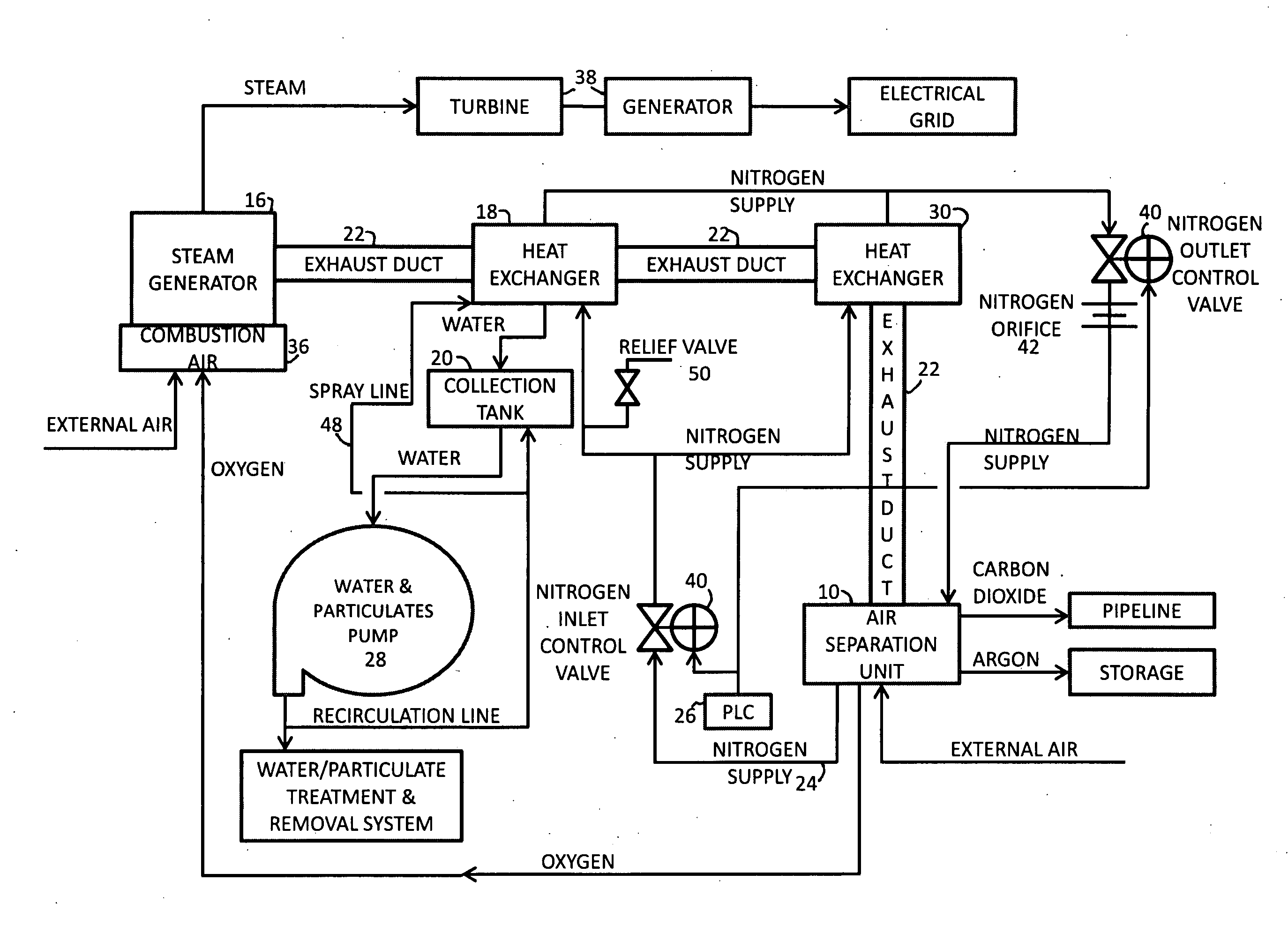
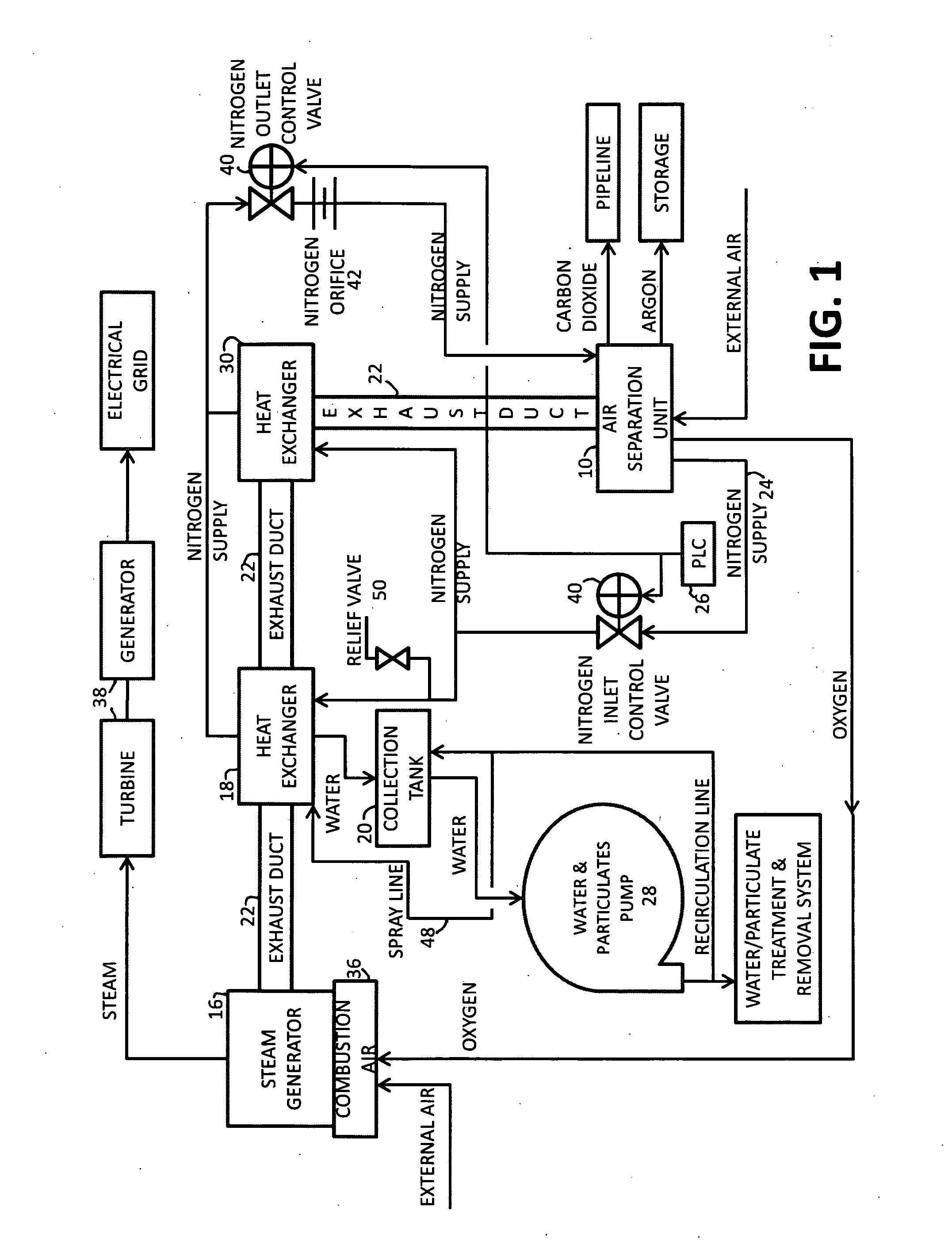
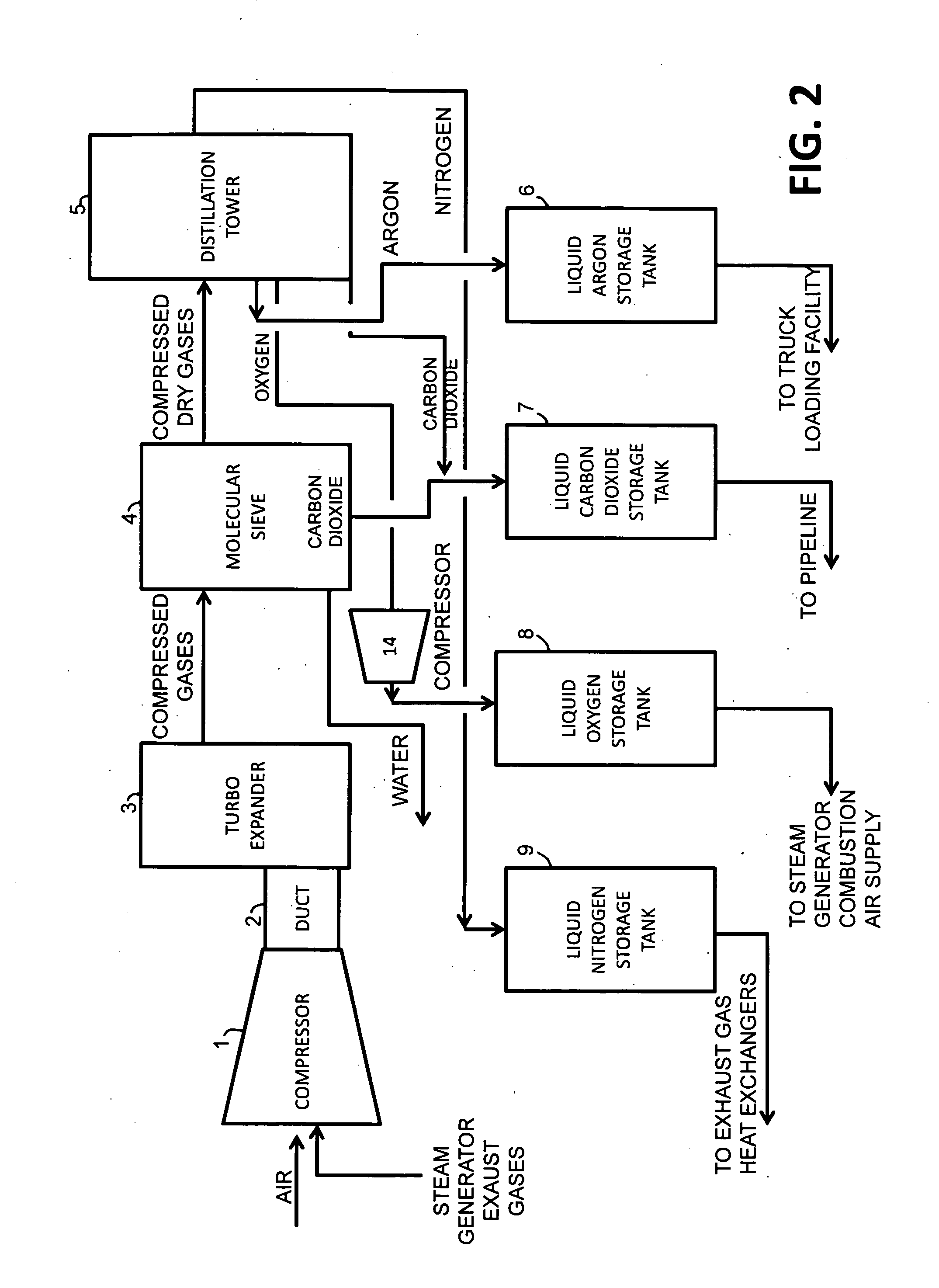
[0019]Basically the invention herein is a power plant comprising: an air separation unit 10 arranged to separate nitrogen, oxygen, carbon dioxide, and argon from air and steam generator exhaust gases and produce a stream of substantially pure liquid nitrogen, oxygen, carbon dioxide, argon, and other trace gases; and a steam generator 16 (or heat recovery steam generator) arranged to combust a fuel in the...


PUM


Abstract

A power plant including an air separation unit (ASU) arranged to separate nitrogen, oxygen, carbon dioxide and argon from air and produce a stream of substantially pure liquid oxygen, nitrogen, carbon dioxide and argon; a steam generator, fired or unfired, arranged to combust a fuel, e.g., natural gas, liquefied natural gas, synthesis gas, coal, petroleum coke, biomass, municipal solid waste or any other gaseous, liquid or solid fuel in the presence of air and a quantity of substantially pure oxygen gas to produce an exhaust gas comprising water, carbon dioxide, carbon monoxide, nitrogen oxides, nitrogen, sulfur oxides and other trace gases, and a steam-turbine-generator to produce electricity, a primary gas heat exchanger unit for particulate/acid gas/moisture removal and a secondary heat exchanger arranged to cool the remainder of the exhaust gases from the steam generator. Exhaust gases are liquefied in the ASU thereby recovering carbon dioxide, nitrogen oxides, nitrogen, sulfur oxides, oxygen, and all other trace gases from the steam generator exhaust gas stream. The cooled gases are liquefied in the ASU and separated for sale or re-use in the power plant. Carbon dioxide liquid is transported from the plant for use in enhanced oil recovery or for other commercial use. Carbon dioxide removal is accomplished in the ASU by cryogenic separation of the gases, after directing the stream of liquid nitrogen from the air separation unit to the exhaust gas heat exchanger units to cool all of the exhaust gases including carbon dioxide, carbon monoxide, nitrogen oxides, nitrogen, oxygen, sulfur oxides, and other trace gases.

Description

BACKGROUND OF THE INVENTION[0001]1. Field of the Invention[0002]This invention relates to an improved power plant, i.e., an electrical power generating plant, with complete emissions recovery, producing power that will be transported and sold on the nearest electrical transmission grid or grids.[0003]2. Description of the Related Art[0004]The invention relates to a new or existing improved power plant, i.e., an electrical power generating plant, with complete emissions recovery. The plant of the invention emits no pollutants, and achieves a zero pollutant emission state of operation. Environmental pollution from fossil-fueled power plants is of worldwide concern. Power plants emit air pollutants such as, toxic metals and hydrocarbons; precursors to acid rain, e.g., sulfur oxides such as sulfur dioxide (SO2), and nitrogen oxides; precursors to ozone such as NO2 and reactive organic gases; particulate matter; and greenhouse gases, notably CO2.[0005]Although certain methods and technol...

Claims


Application Information

Patent Timeline
IPC IPC(8): F02C6/00F02C6/06F25J3/00F01N3/01F02C3/22F02C3/34
CPCF01K3/20F25J2260/80F02C3/22F02C3/34F02C6/04F02C6/06F25J3/04351F25J3/04533F25J3/04563F25J3/04593F25J3/04612F25J3/04648F25J2210/04F25J2210/70F25J2240/70F25J2260/44F01K13/00Y02E20/34
Inventor RILEY, HORACE E.BOYD, THOMAS E.
Owner TRIENCON SERVICES
Why Eureka
Try Eureka