
Intravascular stent

a stent and vascular technology, applied in the field of vascular repair devices, can solve the problems of stents catching on balloons, contributing to plaque prolapse, low conformability, etc., and achieve the effects of reducing the variation in the length of cylindrical rings, shortening the interval, and improving the conformability of stents

Inactive Publication Date: 2005-01-25
ABBOTT CARDIOVASCULAR
View PDF298 Cites 422 Cited by
  • Summary
  • Abstract
  • Description
  • Claims
  • Application Information

AI Technical Summary

Benefits of technology

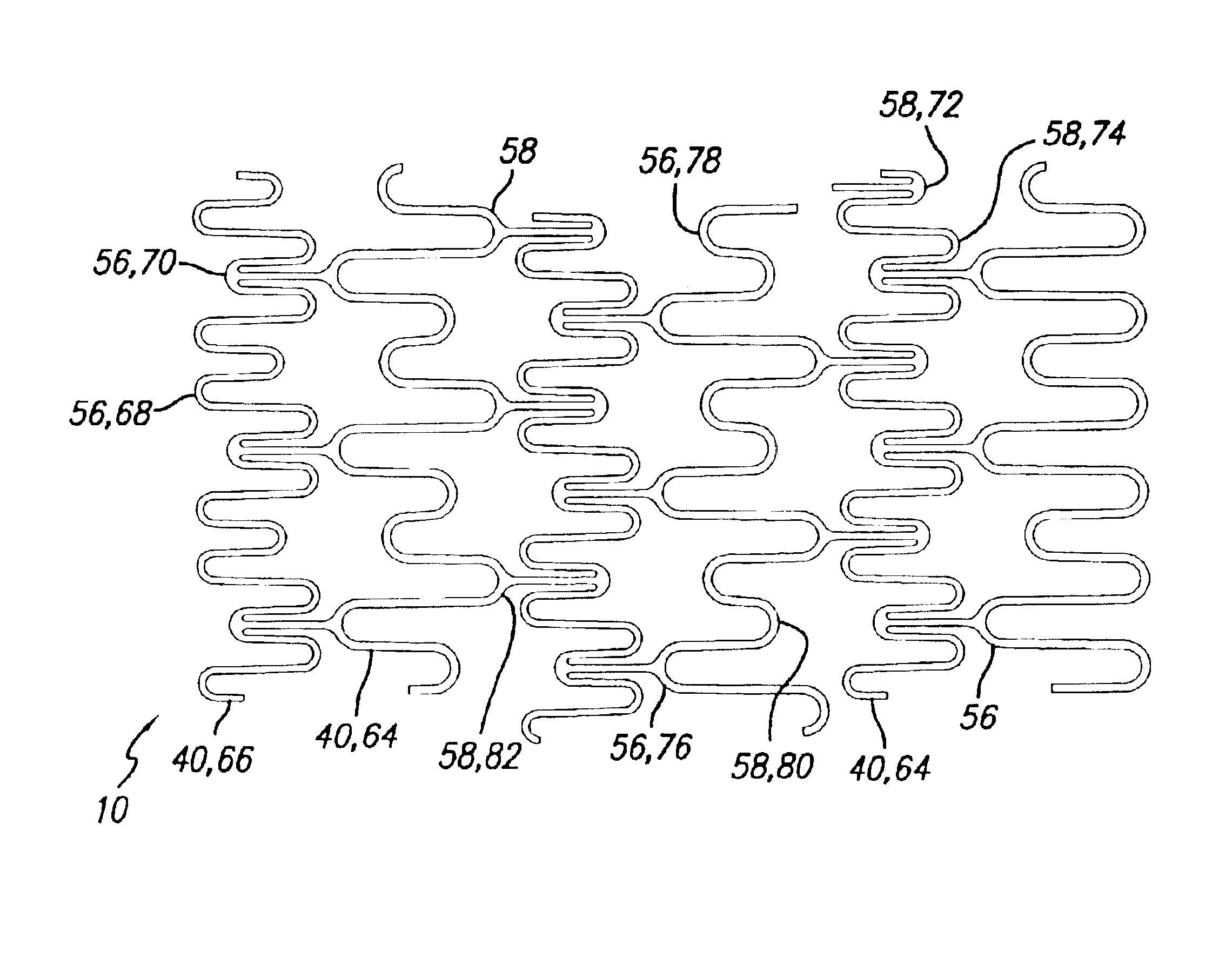
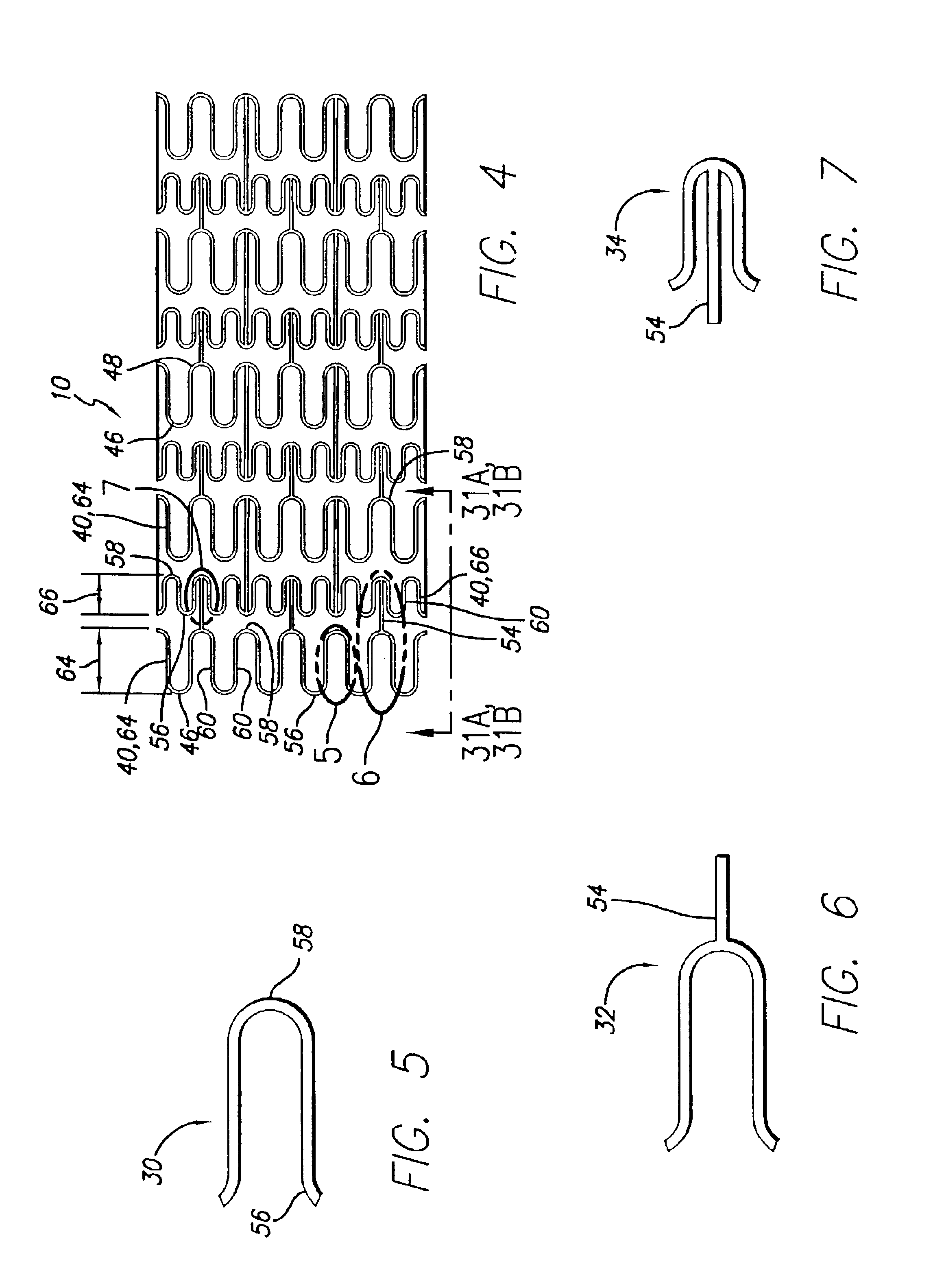
The present invention is directed to an intravascular stent with reduced variation in the length of the cylindrical rings and having shorter intervals for the link patterns, thereby improving conformability of the stent. The invention is also directed to a stent having no unsupported peaks and valleys pointing directly at each other. The invention is further directed at a stent having an increased distance between unsupported peaks and valleys which point directly at each other.
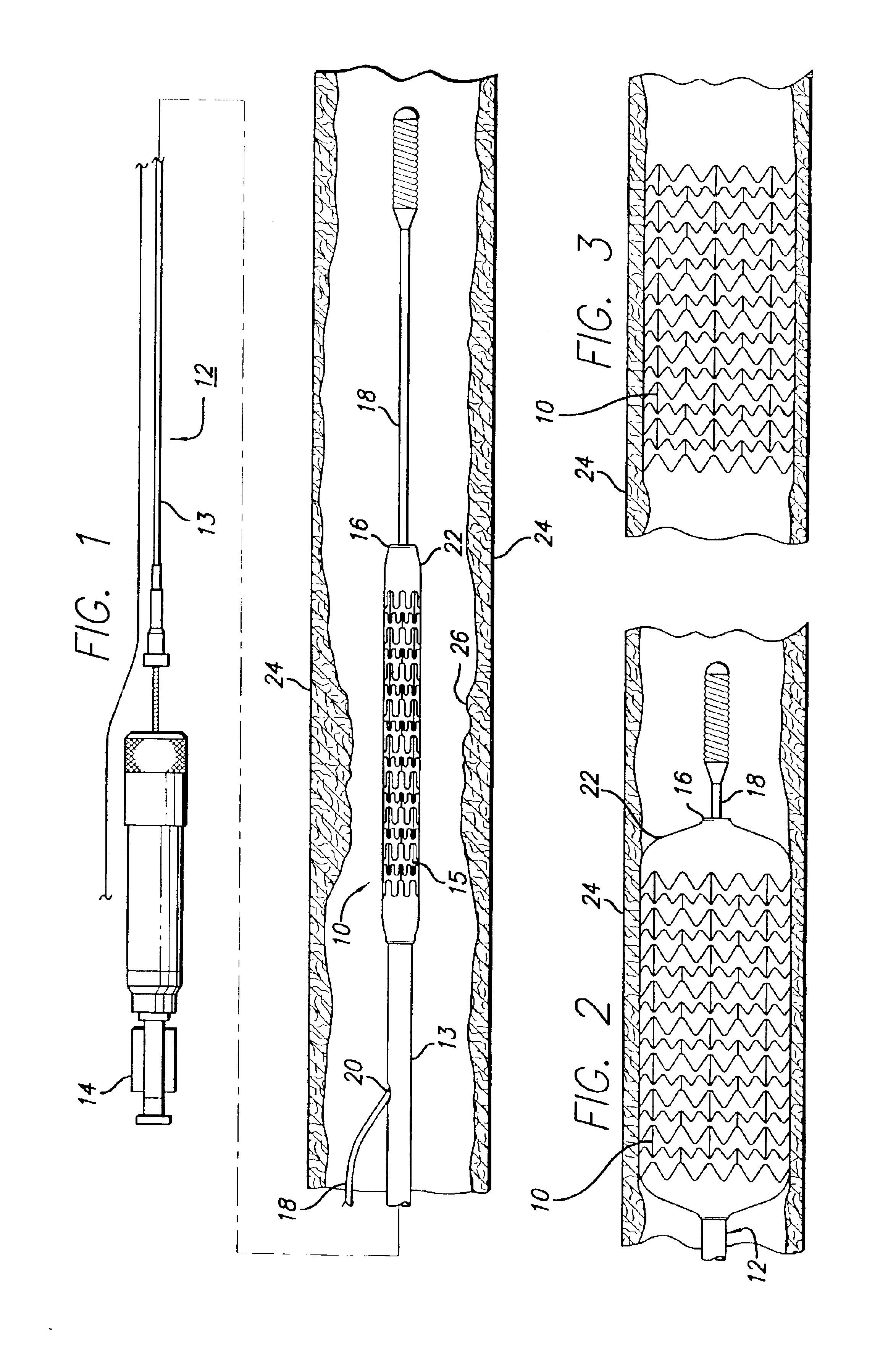
The stent assembly embodying features of the invention can be readily delivered to the desired body lumen, such as a coronary artery (peripheral vessels, bile ducts, etc.), by mounting the stent assembly onto an expandable member of a delivery catheter, for example a balloon, and advancing the catheter and stent assembly through the body lumen to the target site. Generally, the stent is crimped onto the balloon portion of the catheter so that the stent assembly does not move longitudinally relative to the balloon portion of the catheter during delivery through the arteries, and during expansion of the stent at the target site. The stent is relatively flexible along its longitudinal axis to facilitate delivery through tortuous body lumens, yet is stiff and stable enough radially in an expanded condition to maintain the patency of a body lumen, such as an artery, when implanted therein.
While the cylindrical rings and links incorporated into the stent are generally not separate structures, they have been conveniently referred to as rings and links for ease of identification. Further, the cylindrical rings can be thought of as comprising a series of U-, Y- and W-shaped structures in a repeating pattern. While the cylindrical rings are not divided up or segmented into U's, Y's and W's, the pattern of cylindrical rings resembles such configuration. The U's, Y's and W's promote flexibility in the stent primarily by flexing and may tip radially outwardly as the stent is delivered through a tortuous vessel.
Preferably, the number, shape and location of the links can be varied in order to develop the desired coverage area and longitudinal flexibility. These properties are important to minimize alteration of the natural physiology of the body lumen into which the stent is implanted and to maintain the compliance of the body lumen which is internally supported by the stent. Generally, the greater the longitudinal flexibility of the stents, the easier and the more safely they can be delivered to the implantation site, especially where the implantation site is on a curved section of a body lumen, such as a coronary artery or a peripheral blood vessel, and especially saphenous veins and larger vessels.

Problems solved by technology

Some stents have link patterns which repeat themselves over long intervals, thus leading to lower conformability.
The overlap may also cause the stent to catch on the balloon.
Flaring, on the other hand, is a known contributor to plaque prolapse.

Method used


Image

  • Intravascular stent
  • Intravascular stent
  • Intravascular stent

Examples


Embodiment Construction

Before describing in detail an exemplary embodiment of a stent in accordance with the present invention, it is instructive to briefly describe a typical stent implantation procedure and the vascular conditions which are typically treated with stents. Turning to the drawings, FIG. 1 depicts stent 10 of the present invention mounted on a catheter assembly 12 which is used to deliver the stent and implant it in a body lumen, such as a coronary artery, peripheral artery, or other vessel or lumen within the body. The catheter assembly includes a catheter shaft 13 which has a first, proximal end 14 and a second, distal end 16. The catheter assembly is configured to advance through the patient's vascular system by advancing over a guide wire 18 by any of the well known methods of an over the wire system (not shown) or a well known rapid exchange catheter system, such as the one shown in FIG. 1.

The catheter assembly 12, as depicted in FIG. 1, is of the well known rapid exchange (RX) type wh...


PUM


Abstract

An intravascular stent assembly for implantation in a body vessel, such as a coronary artery, includes undulating circumferential rings having peaks on the proximal end and valleys on the distal end. Adjacent rings are coupled together by links. The rings and links are arranged so that the stent has good conformability as it traverses through, or is deployed in, a tortuous body lumen. The stent is also configured such that the likelihood of peaks and valleys on adjacent rings which point directly at each other to overlap in tortuous body vessels is reduced.

Description

BACKGROUND OF THE INVENTIONThis invention relates to vascular repair devices, and in particular to intravascular stents, which are adapted to be implanted into a patient's body lumen, such as a blood vessel or coronary artery, to maintain the patency thereof. Stents are particularly useful in the treatment of atherosclerotic stenosis in arteries and blood vessels.Stents are particularly useful in the treatment and repair of blood vessels after a stenosis has been compressed by percutaneous transluminal coronary angioplasty (PTCA), percutaneous transluminal angioplasty (PTA), or removed by atherectomy or other means, to help improve the results of the procedure and reduce the possibility of restenosis. Stents also can be used to provide primary compression to a stenosis in cases in which no initial PTCA or PTA procedure is performed. While stents are most often used in the procedures mentioned above, they also can be implanted on another body lumen such as the carotid arteries, perip...

Claims


Application Information

Patent Timeline
IPC IPC(8): A61F2/06A61F2/00A61F2/90
CPCA61F2/915A61F2002/91508A61F2002/91516A61F2002/91525A61F2002/91533A61F2230/0054A61F2002/91566A61F2002/91575A61F2250/0036A61F2230/0013A61F2002/91558
Inventor YIP, PHILIP S.TSANG, P. H. WILSONHO, HENJENLIMON, TIMOTHY A.ATLADOTTIR, SVAVA MARIA
Owner ABBOTT CARDIOVASCULAR
Learn More