
Novel polyimide film with improved adhesiveness

a polyimide film, improved technology, applied in the direction of printed circuit aspects, transportation and packaging, chemistry apparatus and processes, etc., can solve the problems of poor adherability, poor adherability, poor adherability, etc., to improve the productivity of the film and suppress thermal distortion

Inactive Publication Date: 2010-01-07
KIKUCHI TAKASHI +1
View PDF27 Cites 2 Cited by
  • Summary
  • Abstract
  • Description
  • Claims
  • Application Information

AI Technical Summary

Benefits of technology

The present invention provides a polyimide film that shows high adherability to metal layers, especially when laminated with an adhesive layer containing a thermoplastic polyimide. This film can prevent thermal distortion and dimensional change during production processes. The invention achieves this by using a specific diamine component and a specific aromatic acid dianhydride component in a polyimide film manufacturing method. The resulting film shows excellent properties, such as high adherability to metal foil, even without surface treatment. The invention also provides a flexible polyimide film that can be easily laminated to metal foil and has good metal-foil peel strength.

Problems solved by technology

Nevertheless, polyimide films obtained by any of theses studies are categorized into films having very poor adherability among plastic films.
In practice, the poor adherability is encountered by performing a surface treatment of various kinds (such as a corona treatment, a plasma treatment, a flaming treatment, a UV treatment, etc.) before providing an adhesive layer on the polyimide films.
While there are various hypotheses for the poor adherability of the polyimide films, it is said that formation of a weak boundary layer (WBL) on the film surface in the process of film formation is one of the causes of the poor adherability.
That is, boundary peeling occurs at the WBL, thereby deteriorating the adherability.
It is expected that requirements in properties such as heat resistance, flexibility, electric reliability, etc. will be more severe, and it will be difficult to satisfy such requirements by using such a thermosetting adhesive agent.
The thermoplastic polyimide is, however, poorer in flowability than thermosetting resins.
As a result, the thermoplastic polyimide cannot get hold of a material and thus is poor in adhesiveness compared with the thermosetting resins.
Therefore, the polyimide film poor in adherability cannot be laminated with sufficient adhesion strength with a metal foil via a thermoplastic polyimide layer poor in adhesiveness.
However, the use of a surface-treated film is associated with such problems as an increase in a number of processes and a higher cost due to the film surface treatment.
The thermoplastic polyimide with the lower glass transition temperature has a problem in that it is poor in heat resistance.
Furthermore, the simultaneous formation of the core layer and the adhesive layer is disadvantageous in that the combination of the core layer and the adhesive layer cannot be changed easily.

Method used


Image

  • Novel polyimide film with improved adhesiveness
  • Novel polyimide film with improved adhesiveness
  • Novel polyimide film with improved adhesiveness

Examples


synthetic example 1

Synthesis of Thermoplastic Polyimide Precursor

[0103]To a 2,000 mL glass flask, 780 g of DMF and 117.2 g of bis[4-(4-aminophenoxy)phenyl]sulfone (hereinafter, also referred to as BAPS) were added. While the resulting mixture was being stirred in a nitrogen atmosphere, 71.7 g of 3,3′4,4′-biphenyltetracarboxylic dianhydride (BPDA) was gradually added to the mixture. Subsequently, 5.6 g of 3,3′,4,4′-ethyleneglycol dibenzoate tetracarboxylic dianhydride (hereinafter, also referred to as TMEG) was added, and the resulting mixture was stirred in an ice bath for 30 minutes. A solution of 5.5 g of TMEG in 20 g of DMF was separately prepared and gradually added to the reaction solution while monitoring the viscosity under stirring. The addition and the stirring were ceased when the viscosity reached 3,000 poise. A polyamic acid solution was thereby obtained.

[0104]The polyamic acid solution thereby obtained was flow-cast on a 25 μm PET film (Cerapeel HP, produced by Toyo Metallizing Co., Ltd.)...

examples 1 to 6

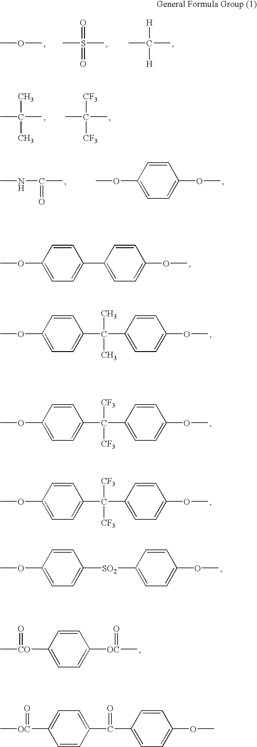
[0105]In a reaction system kept at 5° C., 4,4′-diaminodiphenylether (hereinafter also referred to 4,4′-ODA) and bis{4-(4-aminophenoxy)phenyl}propane (hereinafter also referred to BAPP) in a molar ratio shown in Table 1 were added to N,N-dimethylformamide ((hereinafter also referred to DMF), and stirred. After dissolution of 4,4′-ODA and BAPP was visually checked, benzophenonetetracarboxylic dianhydride (hereinafter, also referred to as BTDA) was added in a molar ratio shown in Table 1 and stirred for thirty minutes.

[0106]Then, pyromellitic dianhydride (hereinafter, also referred to as PMDA) was added in a molar ratio shown in Table 1 “PMDA (1st)” and stirred for thirty minutes. Thereby, a thermoplastic polyimide precursor block component was formed. Subsequently, p-phenylenediamine (hereinafter, also referred to as p-PDA) was added in a molar ratio shown in Table 1 and dissolved therein. Subsequently, PMDA was again added in a molar ratio shown in Table 1 “PMDA (2nd)” and stirred fo...

reference example 1

[0112]A polyimide film of 18 μm in thickness was prepared in the same manner as in Example 1, except that the polymerization of the polyamic acid was carried out with 3,4′-diaminodiphenylether (also referred to as “3,4′-ODA”) instead of 4,4′-ODA. In Reference Example 1, it took 25 hours from the start of the polymerization to obtain a film of 10,000 m long.


PUM

PropertyMeasurementUnit
mol %aaaaaaaaaa
peel strengthaaaaaaaaaa

Abstract

Disclosed is a polyimide film which exhibits high adherability to a metal foil via an adhesive layer containing a thermoplastic polyimide without requiring a special surface treatment. Specifically disclosed is a non-thermoplastic polyimide film obtained by imidizing a polyamic acid solution which is obtained from aromatic diamine and aromatic acid dianhydride. This non-thermoplastic polyimide film is characterized in that the aromatic diamine contains 4,4′-diaminodiphenylether and bis{4-(4-aminophenoxy)phenyl}propane, and the solution containing a polyamic acid is obtained by a specific production method.

Description

CROSS REFERENCE TO RELATED APPLICATION(S)[0001]This application is a continuation of application Ser. No. 11 / 795,222, filed Jul. 12, 2007 and published as U.S. Patent Application No. 2008 / 0097073 A1 on Apr. 24, 2008.TECHNICAL FIELD[0002]The present invention relates to a novel polyimide film having a high adherability (ability of allowing adhesion thereto) without requiring a special surface treatment to its film surface.BACKGROUND ART[0003]The recent trends toward lighter, smaller, and higher-density electronic products have increased the demand for various printed circuit boards. In particular, the demand for a flexible printing wiring board (hereinafter, also referred to as “FPC)”) has shown a notable increase. The flexible printed wiring board is constituted from an insulating film and a circuit formed from a metal foil disposed on the film.[0004]Typically, the flexible metal-clad laminate, from which the flexible printing circuit board is produced, is produced by bonding a meta...

Claims


Application Information

Patent Timeline
Patent Type & Authority Applications(United States)
IPC IPC(8): C08G69/26B32B15/04
CPCB32B15/08C08G73/1007C08J5/18H05K2201/0154C09J179/08H05K1/0346H05K3/386C08J2379/00Y10T428/31678C08G73/10
Inventor KIKUCHI, TAKASHIKANESHIRO, HISAYASU
Owner KIKUCHI TAKASHI
Learn More