
Material With Core-Shell Structure

a core-shell structure and material technology, applied in the field of materials, can solve the problems of battery specifications not being met using traditional lithium-ion battery chemistries, battery energy requirements are continually increasing, and volume and mass constraints remain presen

Inactive Publication Date: 2009-12-24
TOYOTA MOTOR ENGINEERING & MANUFACTURING NORTH AMERICA +1
View PDF14 Cites 13 Cited by
  • Summary
  • Abstract
  • Description
  • Claims
  • Application Information

AI Technical Summary

Benefits of technology

[0006]Disclosed is a material having a composite particle. The composite particle includes an outer shell containing an element such as carbon, nitrogen, oxygen or sulfur and an inner core made from a lithium alloying material such as tin, silicon, aluminum and/or germanium. If the outer shell is made ...

Problems solved by technology

The energy requirements for batteries are continually increasing, while constraints on volume and mass continue to be present.
These demands and battery specifications cannot be met using traditional lithium-ion battery chemistries.
Although lithium-ion batteries have long been optimized and have demonstrated stable energies, these systems are limited by the amount of lithium that can be reversibly inserted and removed from the battery's active material structure.
Research has demonstrated that there are two main issues with the use of a tin-based anode.
The first is a poor cycle life and the second is a poor utilization of the tin.
A poor cycle life is defined as poor retention of battery energy as a function of the number of charge-discharge cycles.
However, the prior research has failed to address the fundamental causes of the poor performance of lithium-tin batteries, which are: 1) a large volume expansion of the tin-lithium particles resulting from the alloying of lithium with tin on charge; and 2) the breaking apart of tin agglomerates during the above-stated volume expansion.
This fresh surface area is not in contact with the matrix, and thus like the separation of tin particles from the matrix, results in decrease in battery capacity.

Method used


Image

  • Material With Core-Shell Structure
  • Material With Core-Shell Structure

Examples


example

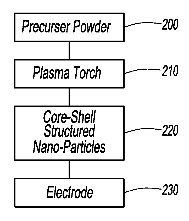
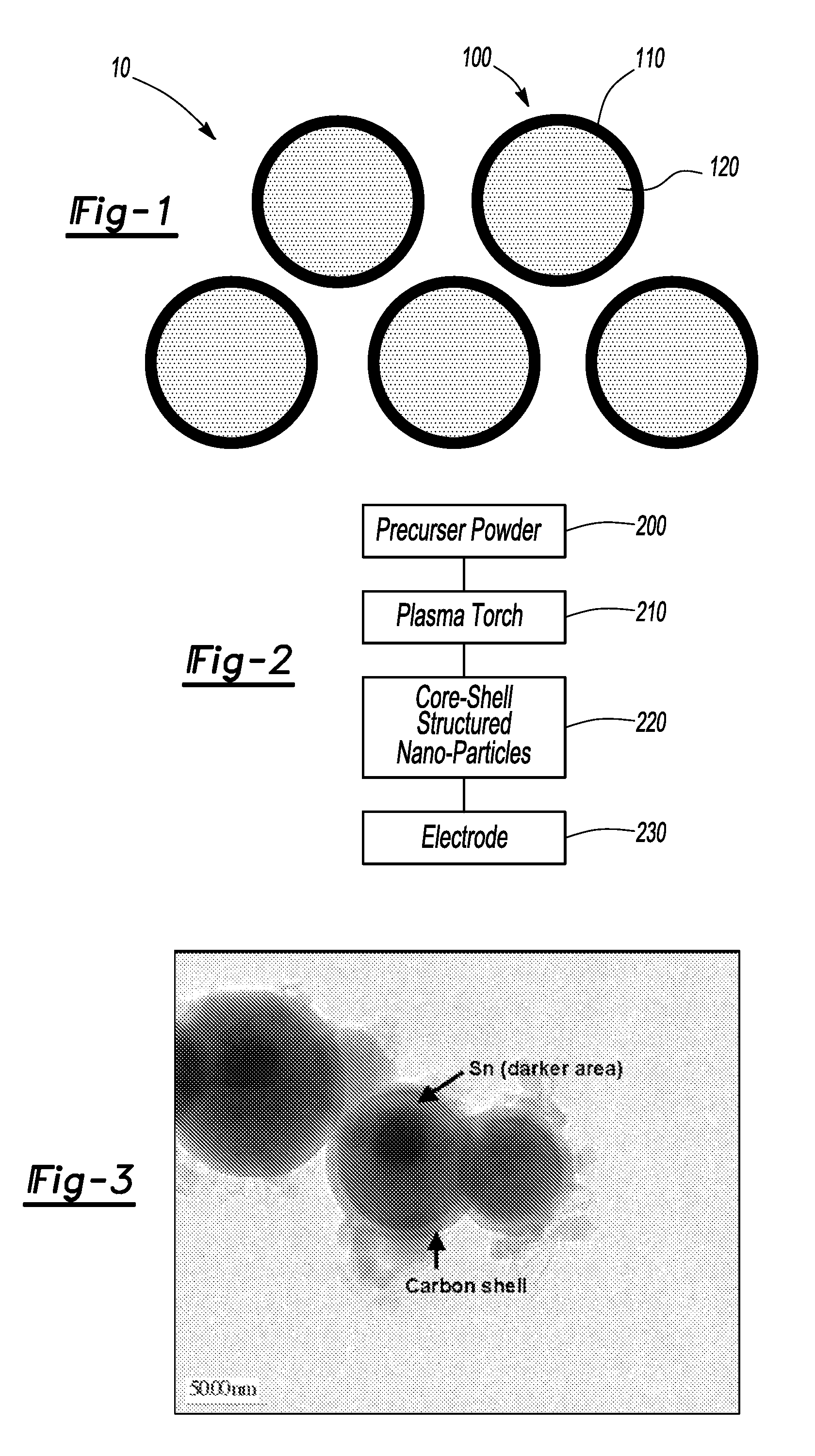
[0018]In an attempt to produce a carbon shell-tin core composite particle, a dry precursor powder was prepared having a tin to anthracene ratio of 50:1. It is appreciated that other aromatic coke forming compounds such as naphthalene or acenaphthalene can be used for providing the carbon material. The precursor powder was suspended in an argon gas, thereby producing an aerosol gas of argon with anthracene and tin. The aerosol gas was passed through a low power atmospheric or near atmospheric pressure plasma with microwave energy focused within a coupler. It is appreciated that plasmas generated using other methods can also be used. In addition to the aerosol gas, a second supply of argon gas was passed through the plasma area.

[0019]Not being bound by theory, the inventors postulate that upon passing through the plasma hot zone, the carbon within the precursor powder undergoes a carbonization mechanism forming carbon fragments. In addition, the tin within the precursor powder melts a...


PUM

PropertyMeasurementUnit
Thicknessaaaaaaaaaa
Thicknessaaaaaaaaaa
Diameteraaaaaaaaaa

Abstract

Disclosed is a material having a composite particle. The composite particle includes an outer shell containing an element such as carbon, nitrogen, oxygen or sulfur and an inner core made from a lithium alloying material such as tin, silicon, aluminum and / or germanium. If the outer shell is made from carbon, the outer shell of the composite particle has an average thickness of less than 20 nanometers and the composite particle has an outer mean diameter of less than 100 nanometers. In some instances, the inner core is made from tin, a tin binary alloy, a tin tertiary alloy or a tin quaternary alloy.

Description

GOVERNMENT INTEREST[0001]This invention was made with government support under Contract No. DE-AC52-06NA25396 awarded by the U.S. Department of Energy. The government has certain rights in the invention.FIELD OF THE INVENTION[0002]The present invention relates to a material, in particular to a material having a core-shell structure.BACKGROUND OF THE INVENTION[0003]The energy requirements for batteries are continually increasing, while constraints on volume and mass continue to be present. Further, the demand for safe, low cost and environmentally friendly materials is increasing. These demands and battery specifications cannot be met using traditional lithium-ion battery chemistries. Although lithium-ion batteries have long been optimized and have demonstrated stable energies, these systems are limited by the amount of lithium that can be reversibly inserted and removed from the battery's active material structure.[0004]The requirements for greater performance, safety, low cost and ...

Claims


Application Information

Patent Timeline
IPC IPC(8): H01M4/38B32B15/04B22F1/16
CPCB22F1/02H01M4/02H01M4/134H01M4/366H01M4/40Y10T428/2991H01M4/621H01M10/0525H01M2004/021H01M2004/027Y02E60/122H01M4/405B22F1/16H01M4/38H01M4/386H01M4/387Y02E60/10
Inventor LUHRS, CLAUDIAPHILLIPS, JONATHANRICHARD, MONIQUE N.STAMM, KIMBER L.
Owner TOYOTA MOTOR ENGINEERING & MANUFACTURING NORTH AMERICA
Learn More