
Tube-shaped solid polymer fuel cell and method for producing tube-shaped solid polymer fuel cell

a solid polymer and fuel cell technology, applied in the field of the method of producing tube-shaped solid polymer fuel cell, can solve the problems of fuel cell power generation performance limitations, and achieve low power generation performance, high electrical resistance, and power generation performance. performance limi

Inactive Publication Date: 2009-11-19
TOYOTA JIDOSHA KK
View PDF3 Cites 1 Cited by
  • Summary
  • Abstract
  • Description
  • Claims
  • Application Information

AI Technical Summary

Benefits of technology

[0009]Accordingly, an object of the present invention is to provide a tube-type fuel cell having improved gas flowability resulting from the fact that catalyst layers can be produced without blocking the gas channels due to infiltration of the gas channels with a catalyst ink, and having improved power generation performance through suppression of the electrical resistance at the time of operation. An object of the same is to provide a method for producing such fuel cell.
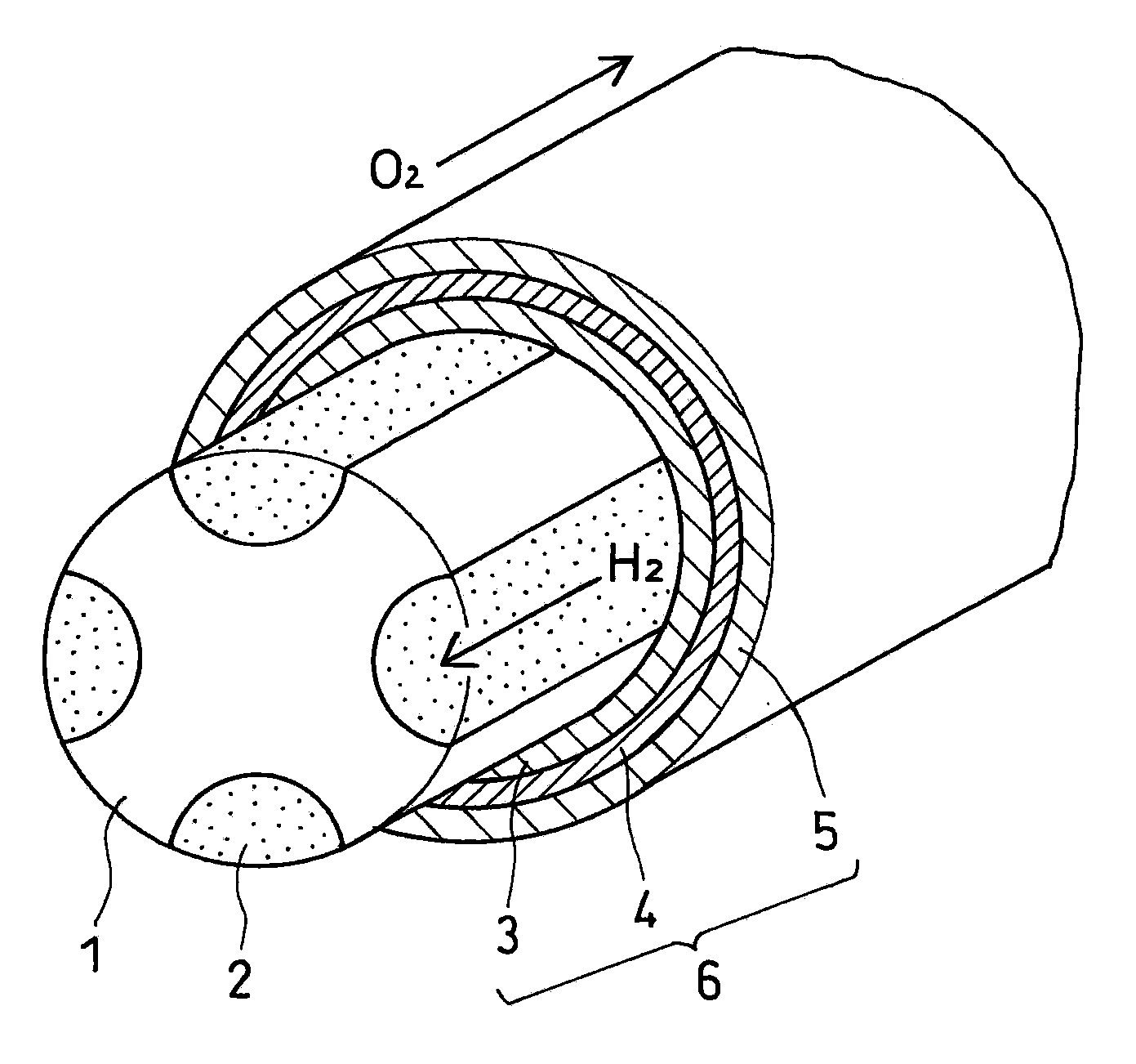
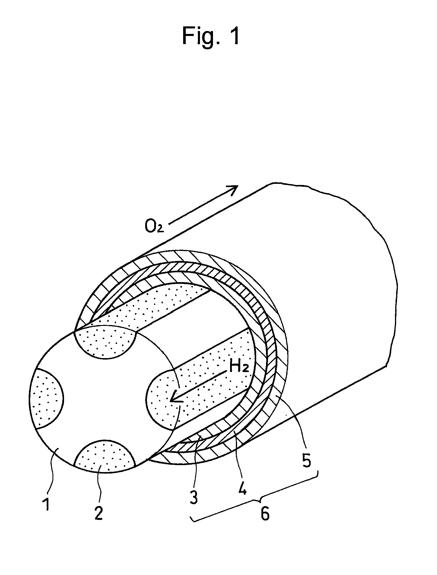
[0011]Specifically, first, the present invention relates to a tube-shaped solid polymer fuel cell which is provided with communicating fuel gas channels on the periphery of a bar-shaped current collector along the axis of the bar-shaped current collector and a membrane-electrode assembly (MEA) on the outside of the bar-shaped current collector and the fuel gas channels and has a structure in which a fuel gas flows through the fuel gas channels and an oxide gas flows outside the membrane-electrode assembly (MEA), wherein:some or all of the fuel gas channels are filled with a porous material having communication pores along the axis thereof and conductive particulates having resistance to corrosion are mixed in with the porous material. The tube-shaped solid polymer fuel cell of the present invention makes it possible to:(1) improve power generation performance in a membrane-electrode assembly (MEA) since fuel gas smoothly penetrates in the porous material that fills in some or all of the fuel gas channels in addition to an oxide gas flowing outside the membrane-electrode assembly (MEA); and(2) improve power generation performance in a membrane-electrode assembly (MEA) since fuel gas channel parts of the inner current collector of the tube-typed fuel cell are not insulators and have electrical conductivity, so as to lower the contact resistance between the current collector and the membrane-electrode assembly (MEA).
[0013]In the present invention, it is more preferable to provide in the porous material a graded structure in which the fine pore size increases from the periphery of the bar-shaped current collector toward the inner current collector side, since the resulting gas diffusivity and drainage are improved.
[0021]Furthermore, the secondary particle size of particles in the catalyst paste to be used for the above step of producing the membrane-electrode assembly (MEA) is preferably 100 nm or more, so as to avoid infiltration of the pores of the porous material.
[0022]Third, the present invention relates to the use of the above tube-shaped solid polymer fuel cell, which is characterized in that it is used as a power source for portable devices. The fuel cell of the present invention can be easily miniaturized, further has high output density, can be expected to have long-term durability, and can be easily handled. Therefore, the fuel cell can be used as a power source for portable electric and / or electronic devices such as telephones, video cameras, and laptop computers or for transportable electric and / or electronic devices.
[0023]According to the present invention, the following effects can be exerted since: communicating fuel gas channels are provided on the periphery of the bar-shaped current collector along the axis of the bar-shaped current collector; some or all of the fuel gas channels are filled with a porous material having communication pores along the axis of the channels; and conductive particulates having resistance to corrosion are mixed in with the porous material.(1) A fuel gas smoothly penetrates in the porous material that fills some or all of the fuel gas channels, and an oxide gas flows outside the membrane-electrode assembly (MEA). As a result, power generation performance in the membrane-electrode assembly (MEA) is improved.(2) Some or all of the fuel gas channels are filled with a porous material, so as to avoid infiltration of the gas channels by a catalyst ink at the time of catalyst layer production and the resulting blocking of the channels. Thus, gas flowability is improved, and this can cause improvement in power generation performance. Alternatively, productivity is improved, since there is no need to remove solid substances filling the gas channels after MEA production.(3) Conductive particulates having resistance to corrosion are mixed in with the porous material, so as to make it possible to impart conductivity to γ-alumina and thus to lower the cell resistance at the time of fuel cell operation.(4) Provision of a graded structure to the porous material via which the fine pore size increases from the periphery of the bar-shaped current collector to the inner current collector side, resulting in improved gas diffusivity and drainage. Thus, power generation performance is further improved.(5) The tube-shaped solid polymer fuel cell of the present invention is a tube-shaped fuel cell with a bar-shaped current collector located in the center. Thus, the fuel cell can cope with miniaturization requirements. In addition to this advantage, through appropriate design of the bar-shaped current collector, tube length, and tube size and through appropriate connecting of units each composed of a tube, a fuel cell capable of dealing with various outputs can be obtained. Porous material portions filling the bar-shaped current collector are excellent in terms of airtightness, so that they are particularly suitable for composing a fuel electrode. In addition, the tube-shaped solid polymer fuel cell of the present invention not only has excellent shape flexibility, but also is capable of keeping strength. Thus, the problems of stack materials, which are problematic in the design of fuel cells, can be addressed.

Problems solved by technology

Tube-type fuel cells according to the conventional art exert a degree of effect in terms of miniaturization, but are problematic in terms of internal gas flowability.
Hence, such fuel cells have limitations in power generation performance.
Furthermore, such fuel cells are also problematic in terms of high electrical resistance during operation of the tube-type fuel cells, resulting in low power generation performance.

Method used


Image

  • Tube-shaped solid polymer fuel cell and method for producing tube-shaped solid polymer fuel cell
  • Tube-shaped solid polymer fuel cell and method for producing tube-shaped solid polymer fuel cell
  • Tube-shaped solid polymer fuel cell and method for producing tube-shaped solid polymer fuel cell

Examples


example 1

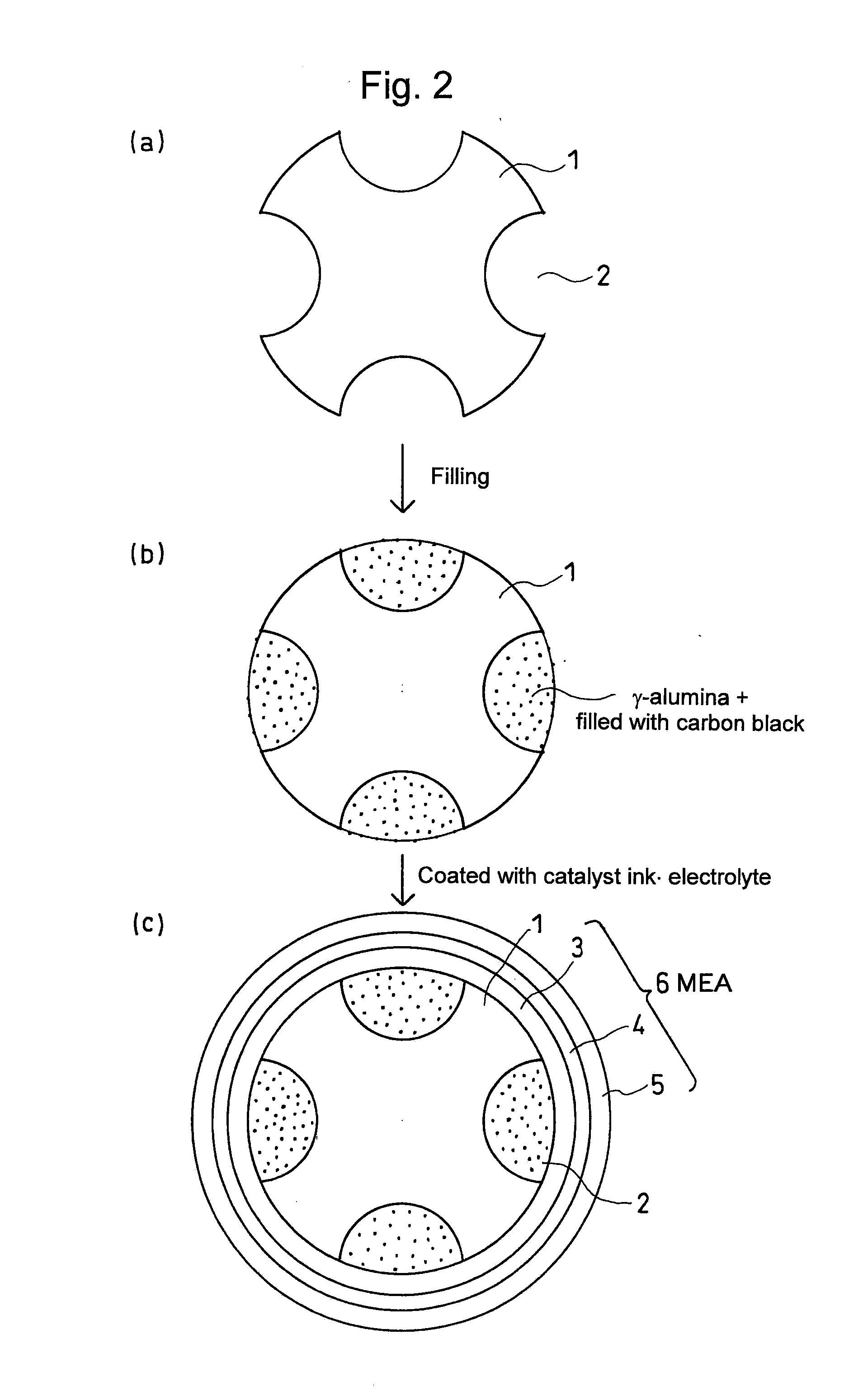
[0039]Similar to comparative example 3, FIG. 5 shows a structure in which slits that are gas channels of an inner current collector in a tube-typed fuel cell are filled with γ-alumina in which conductive particulates having resistance to corrosion are mixed. FIG. 5 also illustrates the production method thereof. In the present invention, to clear the gas channels of the inner current collector and to secure the conductivity of the gas channels, these channels were filled with γ-alumina having fine pores, in which conductive particulates having resistance to corrosion are mixed. The thus obtained structure can prevent infiltration of a catalyst paste at the time of MEA production, can secure the gas diffusivity at the time of electric power generation without requiring any removal step after MEA production, and can reduce cell resistance at the time of fuel cell operation.

[0040]Specifically, conductive particulates having resistance to corrosion, such as carbon powders (e.g., Ketjen ...


PUM

PropertyMeasurementUnit
porosityaaaaaaaaaa
pore sizeaaaaaaaaaa
particle sizeaaaaaaaaaa

Abstract

A tube-shaped solid polymer fuel cell is provided with communicating fuel gas channels 2 on the periphery of a bar-shaped current collector 1 and along the axis of the bar-shaped current collector 1 and the membrane-electrode assembly (MEA) 6 on the outside of the bar-shaped current collector 1 and the fuel gas channels 2 and has a structure in which a fuel gas flows through the fuel gas channels 2 and an oxide gas flows outside the membrane-electrode assembly (MEA) 6, whereinsome or all of the fuel gas channels 2 are filled with a porous material having communication pores along the axis thereof and a conductive particulate having resistance to corrosion is mixed in with the porous material.The tube-shaped solid polymer fuel cell of the present invention makes it possible to improve gas flowability at the time of production of catalyst layers while avoiding infiltration of the gas channels by a catalyst ink so as to block the channels and thus lower cell resistance at the time of fuel cell operation. Thus, power generation performance is improved by the present invention.

Description

TECHNICAL FIELD[0001]The present invention relates to a tube-shaped solid polymer fuel cell that uses a bar-shaped current collector and a method for producing the tube-shaped solid polymer fuel cell.[0002]Fuel cells generate electrical energy that is directly converted and obtained from the chemical energy of fuel through electrochemical oxidation of fuel such as hydrogen or methanol within the cells. In recent years, fuel cells have been attracting attention as clean sources of electrical energy supply. In particular, the use of a solid polymer fuel cell in which a proton exchange membrane is used as an electrolyte enables obtainment of high power density and low-temperature operation. Thus, such solid polymer fuel cell is expected as a power source for mobile vehicles, in addition to a compact fuel cell such as a household stationary power source, a portable appliance, a transportable power source, or the like.[0003]A conventional solid polymer fuel cell is composed by separately...

Claims


Application Information

Patent Timeline
Patent Type & Authority Applications(United States)
IPC IPC(8): H01M8/10B05D5/12
CPCH01M8/004H01M8/0247H01M8/0258Y02E60/521H01M8/1004H01M2008/1095H01M8/04089Y02P70/50Y02E60/50H01M8/026
Inventor HAMA, YUICHIROKURUNGOT, SREEKUMAR
Owner TOYOTA JIDOSHA KK
Learn More