
Integrated circuit having interleaved gridded features, mask set and method for printing

Active Publication Date: 2009-11-05
TEXAS INSTR INC
View PDF14 Cites 140 Cited by
  • Summary
  • Abstract
  • Description
  • Claims
  • Application Information

AI Technical Summary

Benefits of technology

[0012]As used herein, the terms “horizontal”, “vertical”, “rows”, columns”, “x”, and “y” only each serve to each define orientation in one of the orthogo

Problems solved by technology

Various physical effects, principally interference, can be used to help make darkness, but generally forcing photons into a small spot is difficult because of diffraction effects.
Along with microminiaturization of the mask pattern, the influence of the optical proximity effect becomes more pronounced, and consequently, the pattern fidelity deteriorates, thereby causing a problem that the resist pattern is found largely deviated from the mask pattern.
Thus, pattern fidelity is found deteriorated due to these optical proximity effects.
Such random placements (especially isolated or semi-isolated placements) have small depth of focus values, that is, they only fully remove the resist when the resist is almost exactly in the best focus plane of the exposure.
Small depth of focus values are problematic for the desired wide manufacturing margins and can result in yield loss, such as due to highly resistive or electrically open contacts and vias.
Even certain regular feature patterns can be difficult to print, particularly when the pitch (center-to-center feature spacing) becomes small.
However, moving the S / D and gate contacts apart in the vertical direction undesirably lowers the density of the devices on the wafer, thus raising the cost per die.
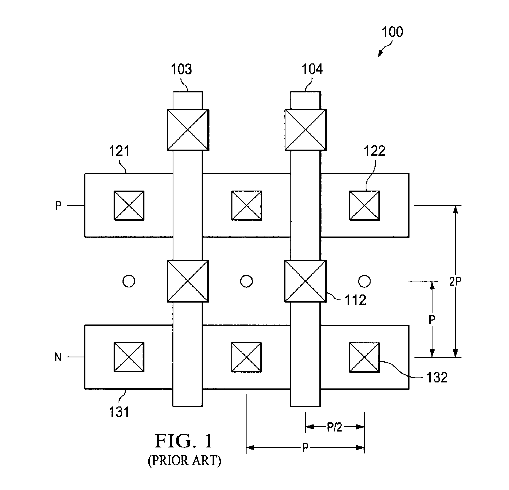
Even in the case where the circuit features are generally periodic over small areas of the circuit, such as the standard cell arrangement shown in FIG. 1, the circuit features may become difficult to print using known printing techniques, particularly if the feature pitch becomes small (e.g. 130 nm), for example when some of the features are at positions less than the feature pitch, such as when some features are nearly at half pitch positions.
Moving the S / D and gates contacts apart in the other direction (e.g. the vertical direction) undesirably lowers density of the devices on the wafer, thus raising the cost per die.

Method used


Image

  • Integrated circuit having interleaved gridded features, mask set and method for printing
  • Integrated circuit having interleaved gridded features, mask set and method for printing
  • Integrated circuit having interleaved gridded features, mask set and method for printing

Examples


Embodiment Construction

[0024]The present invention is described with reference to the attached figures, wherein like reference numerals are used throughout the figures to designate similar or equivalent elements. The figures are not drawn to scale and they are provided merely to illustrate the instant invention. Several aspects of the invention are described below with reference to example applications for illustration. It should be understood that numerous specific details, relationships, and methods are set forth to provide a full understanding of the invention. One having ordinary skill in the relevant art, however, will readily recognize that the invention can be practiced without one or more of the specific details or with other methods. In other instances, well-known structures or operations are not shown in detail to avoid obscuring the invention. The present invention is not limited by the illustrated ordering of acts or events, as some acts may occur in different orders and / or concurrently with o...


PUM


Abstract

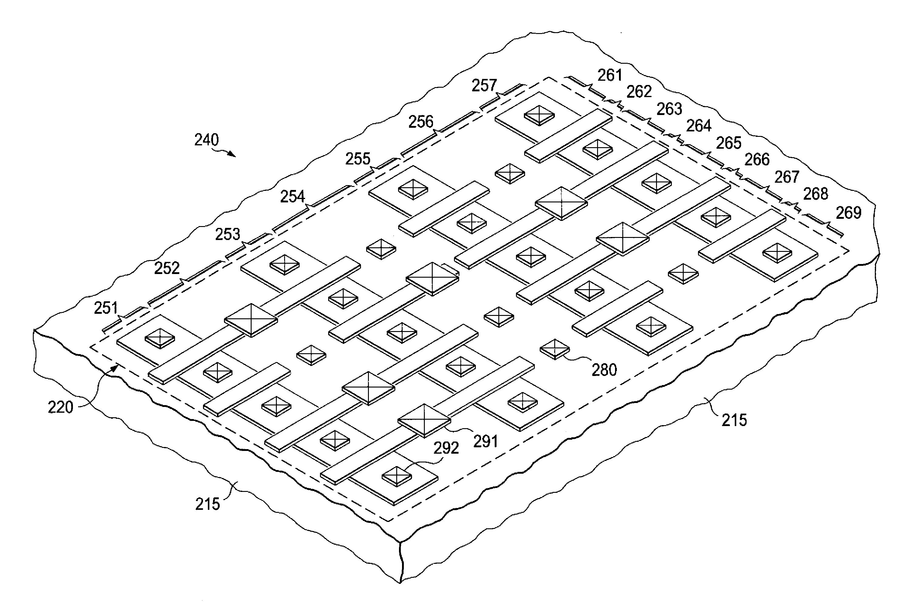
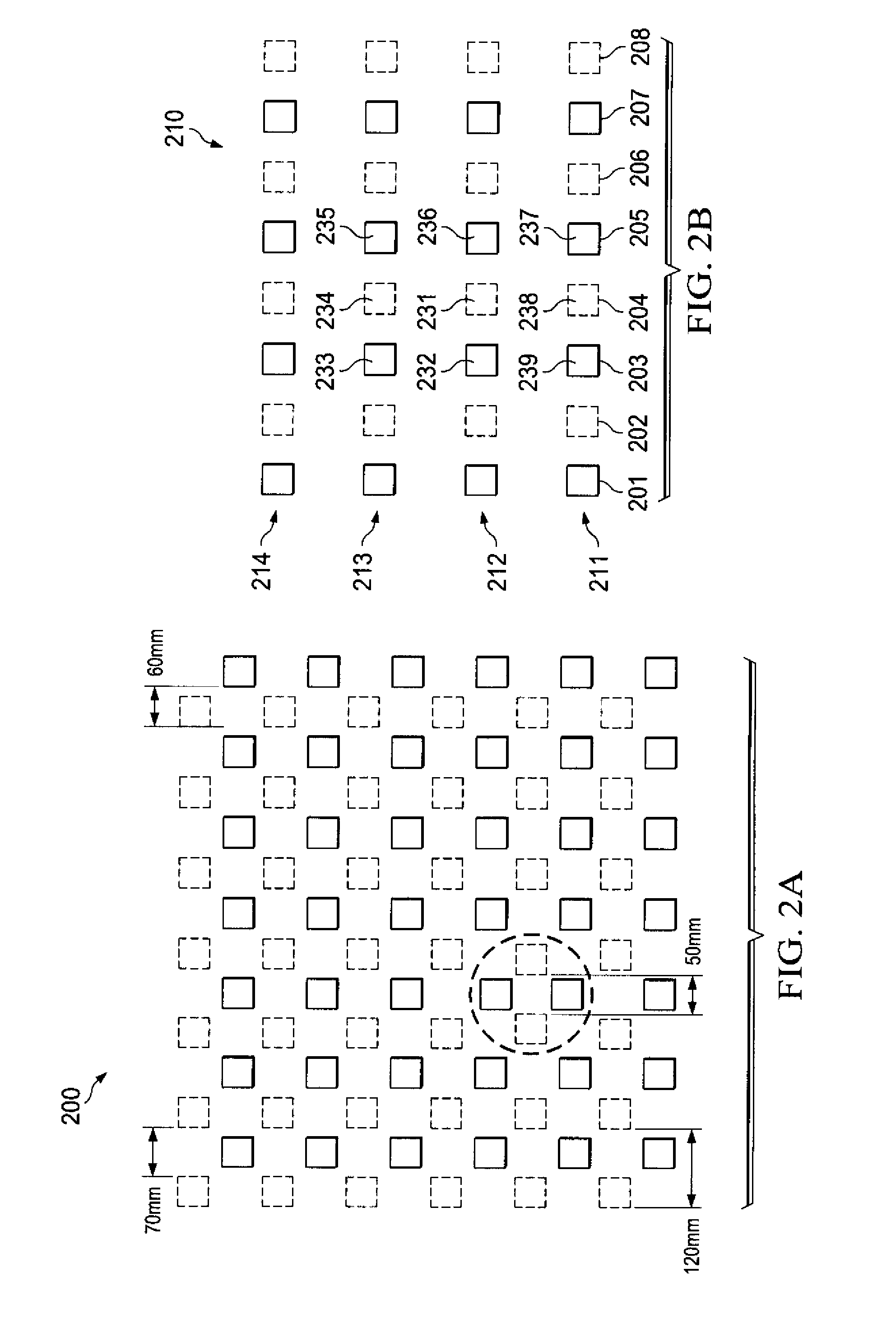
A method (300) for fabricating an integrated circuit includes the step of providing a substrate having a semiconductor surface (305). For at least one masking level (e.g. gate electrode, contact or via) of the integrated circuit, a mask pattern for the masking level is partitioned into a first mask and at least a second mask (310). The first mask provides features in a first grid pattern and the second mask provides features in a second grid pattern. The first and second grid pattern have respective features that interleave with one another over at least one area. A first photoresist film is applied onto the surface of the substrate (315). The first grid pattern is printed using the first mask (320). The second grid pattern is printed using the second mask (325). The first and said second grid pattern are then etched into the surface of the substrate (330). Another embodiment of the invention includes an integrated circuit (240) that has vias or contacts in a grid-like feature pattern in at least one multi-transistor area of the circuit including at least 5 transistors, wherein a minimum horizontal or minimum vertical center-to-center spacing distance between neighboring features in the pattern is ≦100 nm.

Description

FIELD OF THE INVENTION[0001]The present invention relates to semiconductor fabrication and integrated circuits, and more specifically to mask arrangements, circuit layouts and printing processes for forming integrated circuits.BACKGROUND[0002]A photo mask is generally obtained by depositing a Cr (chromium) film on predetermined parts of a glass substrate, serving as light shielding parts. Parts of the glass substrate, not covered with the Cr film, serve as light transmitting parts. Exposure light is transmitted through these light transmitting parts or shielded with these light shielding parts, thus implementing transfer of predetermined mask patterns to a resist or the like as an object for exposure, formed on a semiconductor substrate (wafer). After the transfer of the mask patterns to the resist, patterning is executed on the photoresist, and a semiconductor device is fabricated using the resist as patterned.[0003]The lithography tool's light source provides wavelength limited li...

Claims


Application Information

Patent Timeline
IPC IPC(8): H01L23/48H01L21/311G03F1/00
CPCH01L21/31144H01L27/1104H01L27/11H01L27/0207H10B10/00H10B10/12
Inventor ATON, THOMAS J.PLUMTON, DONALD
Owner TEXAS INSTR INC
Learn More