
Method and apparatus for measuring crossover loss of fuel cell

Inactive Publication Date: 2009-10-01
HITACHI LTD
View PDF1 Cites 5 Cited by
  • Summary
  • Abstract
  • Description
  • Claims
  • Application Information

AI Technical Summary

Benefits of technology

[0012]In view of the above, the present invention has for its object the provision of a novel measuring method of measuring a methanol crossover loss directly.

Problems solved by technology

At present, however, the output of MEA is lower than that of a lithium secondary cell, thus not yet arriving at practice.
This causes an overvoltage to be increased at the cathode owing to the crossover, thereby lowering the output of MEA.

Method used


Image

  • Method and apparatus for measuring crossover loss of fuel cell
  • Method and apparatus for measuring crossover loss of fuel cell
  • Method and apparatus for measuring crossover loss of fuel cell

Examples


first embodiment

[0046]S-PES (ion exchange capacity of 1.3 meq / g) was provided as a membrane. A varnish was prepared by dissolving S-PES (ion exchange capacity of 1.3 meq / g) in dimethylacetamide. The concentration of the solute was set at 30 wt %. The varnish was coated onto a glass sheet by means of an applicator and dried at 80° C. for 1 hour and then at 120° C. for 3 hours in a vacuum dryer, thereby evaporating the dimethylacetamide solvent. Thereafter, the coated film was peeled off from the glass sheet and immersed overnight in a 1M H2SO4 aqueous solution and protonated to obtain a single electrolyte membrane of S-PES (ion exchange capacity of 1.3 meq / g). The thus obtained electrolyte membrane was transparent. The thickness of the electrolyte membrane was at 50 μm.

[0047]MEA was made in the following way. Platinum-bearing carbon TEC10V50E (amount of supported Pt: 50 wt %), made by Tanaka Kikinzoku Kogyo K.K., was provided as a cathode catalyst and platinum and ruthenium-bearing carbon TEC61V54 (...

second embodiment

[0057]Nafion 112 (with a thickness of about 50 μm), made by Du Pont Kabushiki Kaisha, was used as an electrolyte membrane. In the same conditions and procedure as in the First Embodiment, MEA's were made. These MEA's were subjected to measurement of a crossover loss according to the novel crossover measuring method of this embodiment. FIG. 12 shows a crossover loss relative to a methanol concentration. The relation between the crossover loss and the methanol concentration became non-linear.

third embodiment

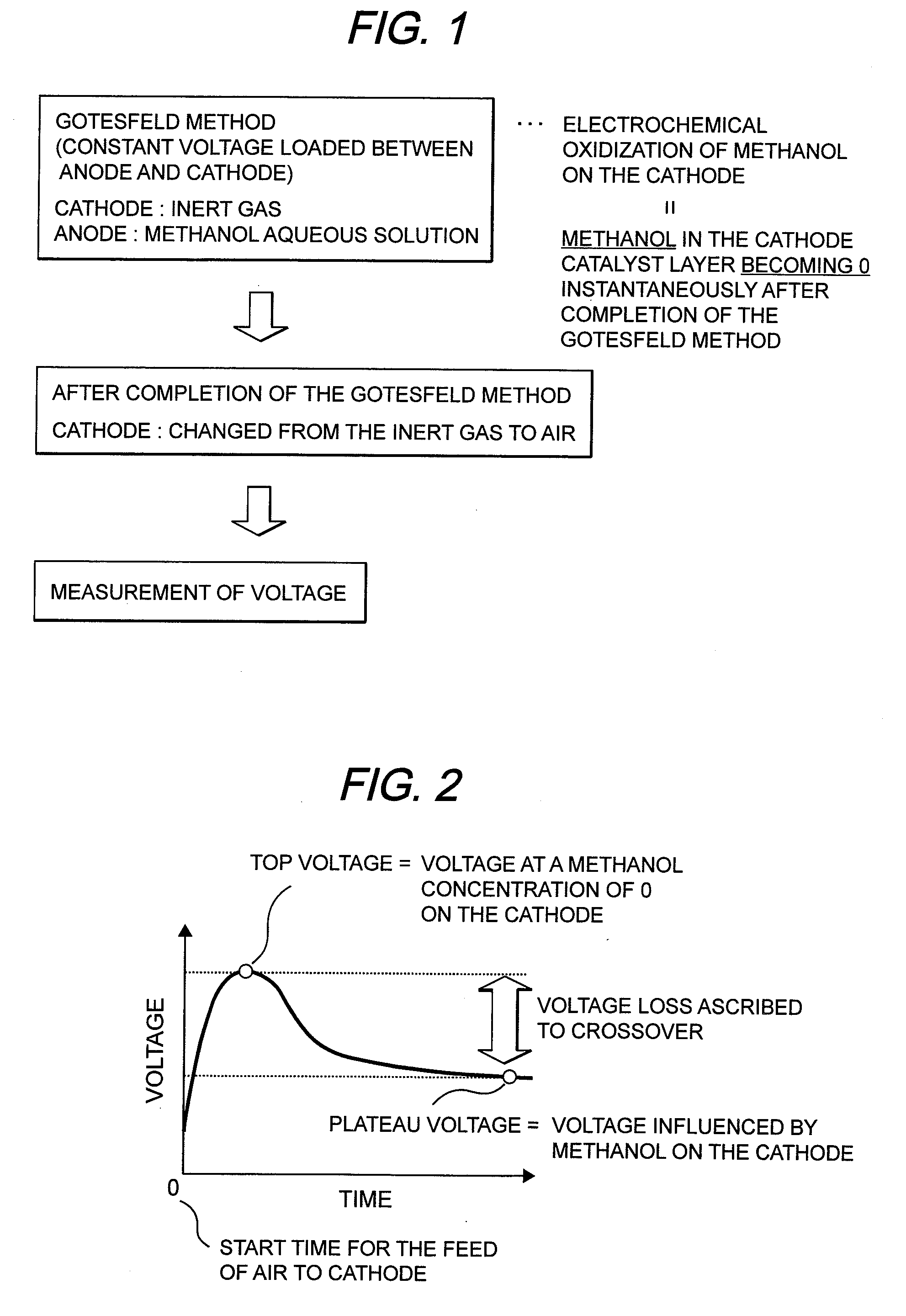
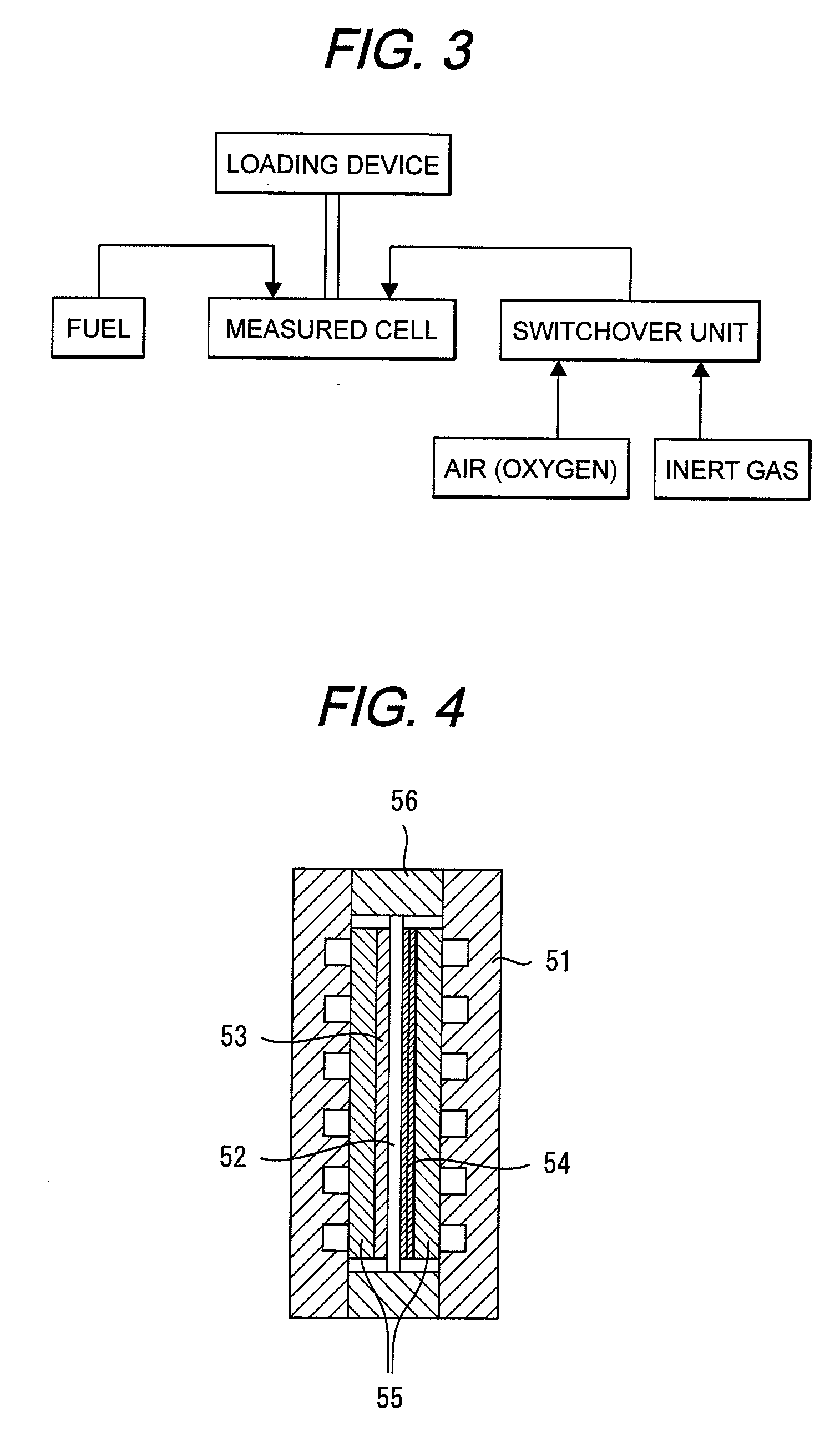
[0059]MEA was made under the same conditions as in the First Embodiment. This MEA was assembled in a cell shown in FIG. 4. The temperature of the cell was set at 70° C. Nitrogen gas was fed to the cathode and hydrogen gas was fed to the anode each at 70° C. after humidification. In this condition, a voltage of 0.8 V was loaded between the anode and the cathode for 10 minutes. A running current density was at 0.3 mA / cm2. Thereafter, air was fed to the cathode in place of the nitrogen gas, followed by measurement of a voltage. As a result, a top voltage was 1100 mv, and a plateau voltage was 1050 mv. As a result, a hydrogen crossover loss obtained was at 50 mV.


PUM


Abstract

When using a measurement of a crossover current density by the Gotesfeld method or a measurement of a methanol permeation coefficient by gas chromatography or by liquid chromatography, a measure for crossover amount may be given but the interrelation with a crossover loss is not clearly known and thus, it could not be possible to evaluate a degree of the crossover loss. The present invention has for its object the provision of a novel measuring method that is able to measure a methanol crossover loss directly.The measuring method is characterized by measuring a crossover loss of MEA for methanol fuel cell from a difference between a voltage when a cathode catalyst layer is not influenced by methanol crossover and a voltage when the cathode catalyst layer is influenced by the methanol crossover.

Description

TECHNICAL FIELD[0001]This invention relates to a novel method for measuring a crossover loss relative to a membrane electrode assembly for fuel cells. The invention also relates to a measuring apparatus based on the measuring method. The invention still relates to various type of application devices based on the measuring method.TECHNICAL BACKGROUND[0002]In recent years, a direct methanol fuel cell DMFC (Direct Methanol Fuel Cell) using methanol as a fuel has been expected as an electric source for portable devices in place of lithium ion secondary cells, and extensive developments have been made in order to work forward the practical use thereof.[0003]The electric generation unit of DMFC has a structure wherein a cathode catalyst layer and an anode catalyst layer are provided on opposite sides of a proton conductive solid polymer electrolyte membrane. This is called membrane electrode assembly (Membrane Electrode Assembly). The cathode catalyst layer and the anode catalyst layer ar...

Claims


Application Information

Patent Timeline
IPC IPC(8): H01M8/04H01M8/10
CPCH01M8/04089H01M8/04186H01M8/04261H01M8/04552Y02E60/523H01M8/04753H01M8/04798H01M8/1011H01M8/04671H01M8/04197Y02E60/50
Inventor HIRASHIGE, TAKAYUKIKAMO, TOMOICHI
Owner HITACHI LTD
Learn More