
Reducing sheet distortion in friction stir processing

a technology of friction stir and friction stir, which is applied in the direction of manufacturing tools, non-electric welding apparatuses, transportation and packaging, etc., can solve the problems of thermal and mechanical distortion of friction stir welded aluminum sheets, distortion of the cooler surrounding metal, and marred visible surfaces of automotive body panels, so as to reduce the yield strength, facilitate unwanted deformation, and high conductivity

Inactive Publication Date: 2009-08-13
GM GLOBAL TECH OPERATIONS LLC
View PDF17 Cites 39 Cited by
  • Summary
  • Abstract
  • Description
  • Claims
  • Application Information

AI Technical Summary

Benefits of technology

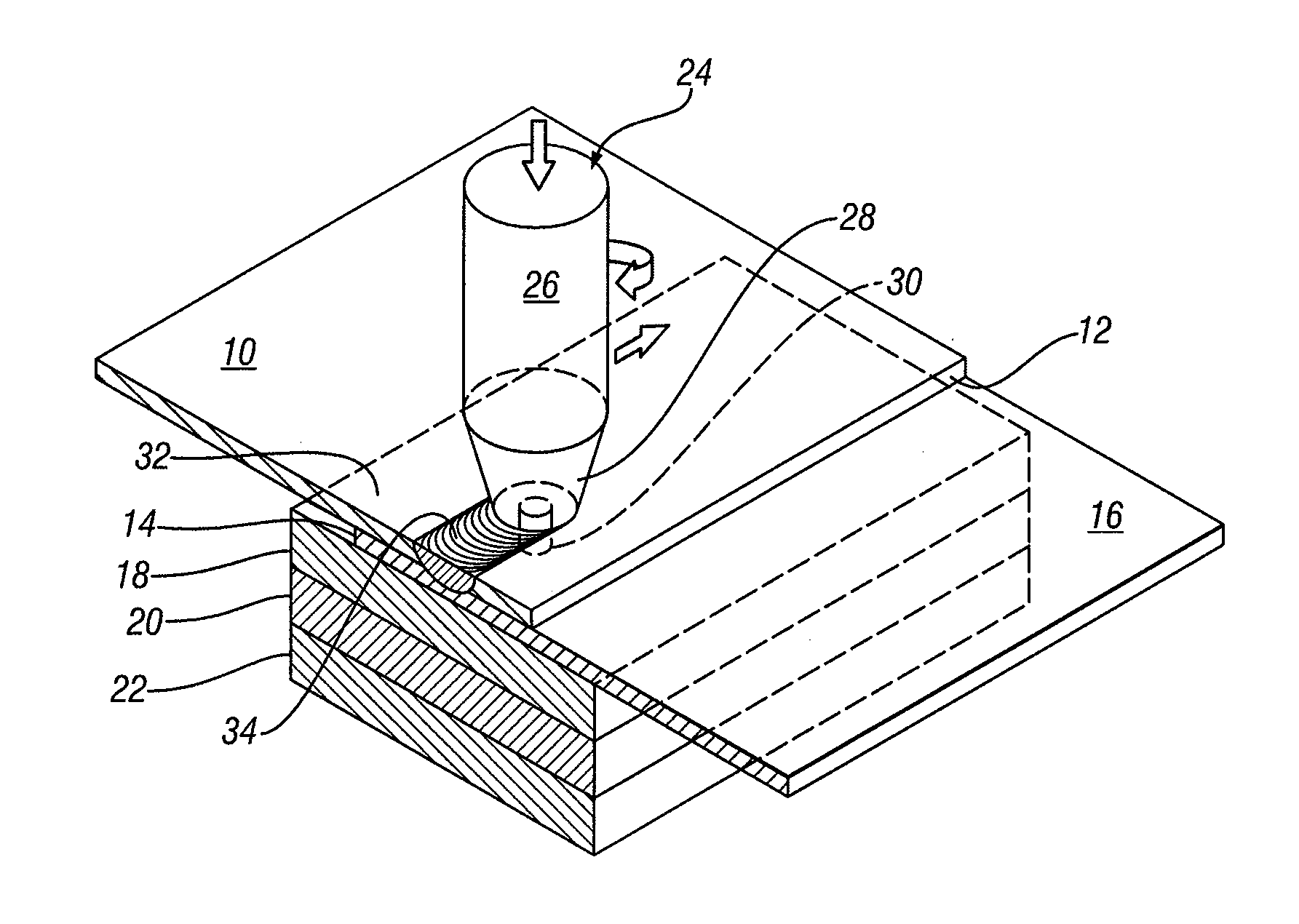
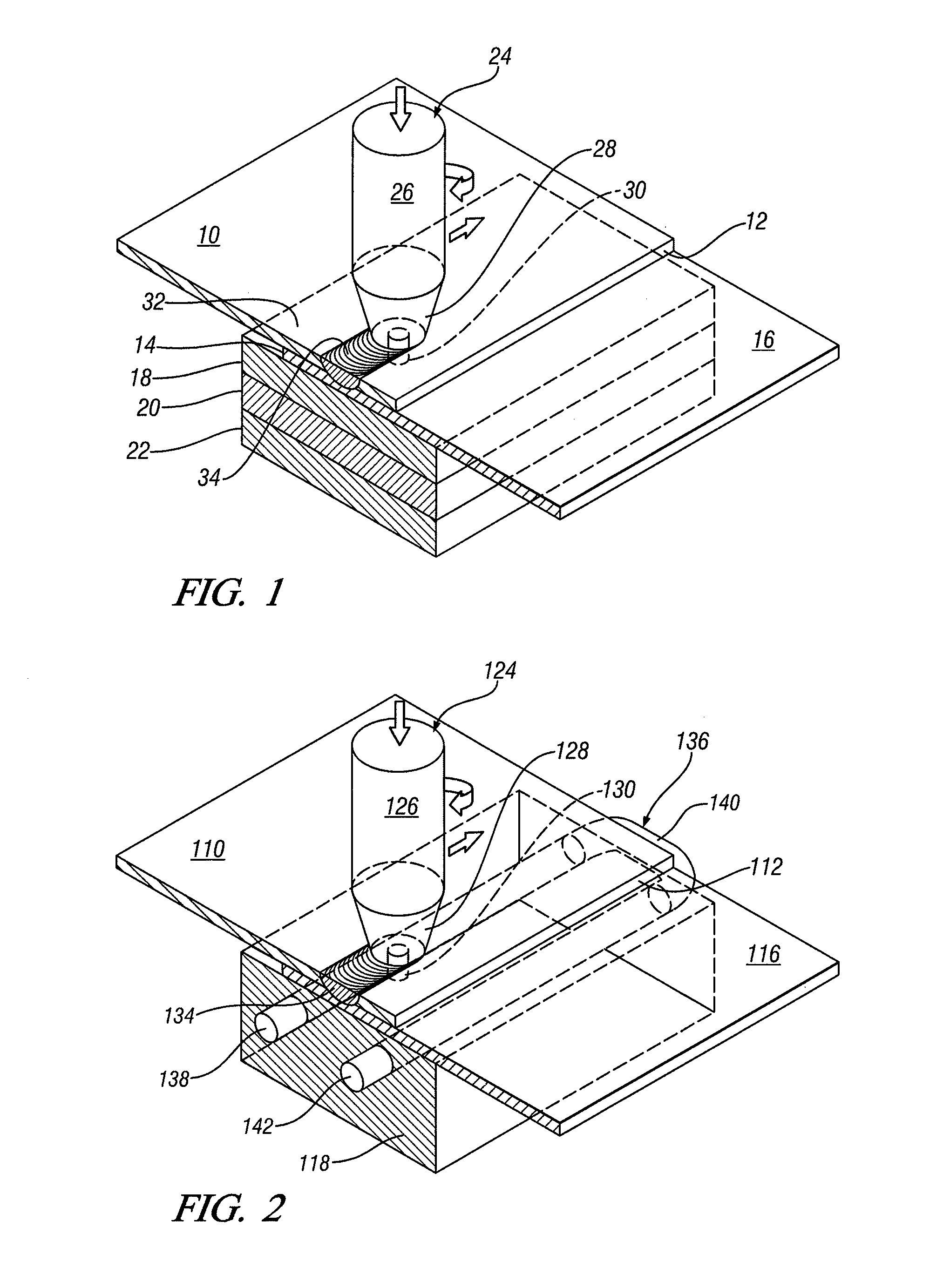
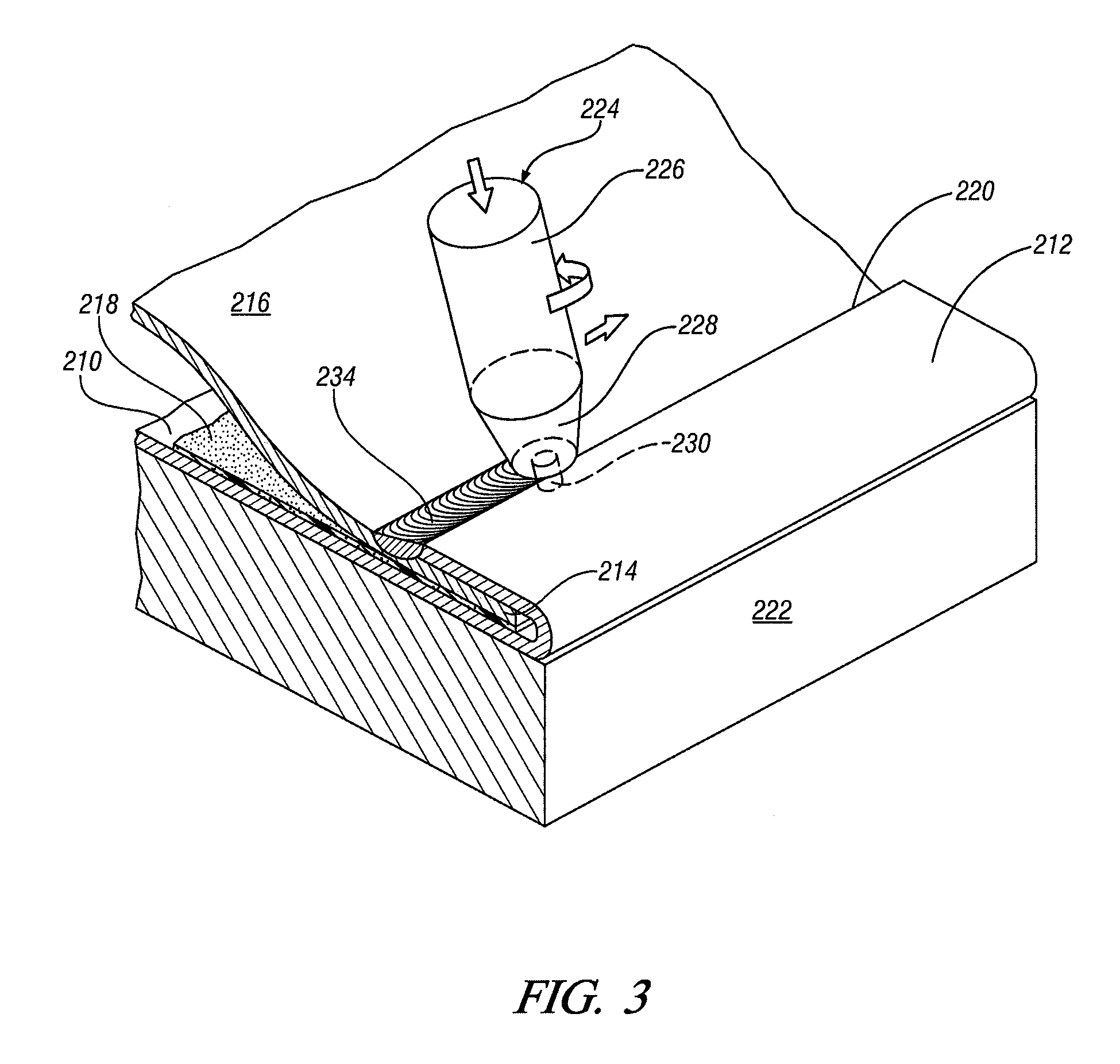
[0007]In friction stir processing a suitable anvil structure supports the workpiece(s) against the applied force of the rotating friction stir tool. In the practice of this invention, the workpieces may often be light metal sheet materials such as aluminum alloy or magnesium alloy vehicle body panels, or other relatively thin metal parts and an anvil is also used to conduct heat from a friction stir processing site. When, for example, a three-layer stack of one millimeter thick aluminum sheets is subjected to friction stir processing, the temperature of plasticized metal may reach 450-470° C. The mass of hot plasticized metal may heat surrounding sheet material so as to reduce its yield strength and enable unwanted deformation. A high conductivity surface of the anvil closely engages a side of the sheet metal workpieces opposite that engaged by the friction stir tool. The anvil is used to remove heat from the work site so as to maintain the contacting workpiece layer at a suitably low temperature (e.g., 300° C. or lower in the case of aluminum alloys) to avoid deformation. In accordance with the invention, an anvil for friction stir processing of sheet metal workpieces is formed of a hard material that also dissipates heat quickly from the sheet material especially at and around the friction stir processing engagement site. For example, an anvil material and structure (which may be internally cooled) is provided so that its heat removal ability into the anvil is greater than an equivalent thermal conductivity of about 40 W / m-° K. at room temperature. Further, in those embodiments in which the anvil side of the workpieces will be a visible surface in a finished product, the anvil is further provided with a suitably smooth surface finish so that the anvil does not damage the visible surface of a friction stir processed article.
[0009]In another embodiment of the invention, the anvil structure may itself be cooled for temperature management of the friction stir processing site in the sheet materials. For example, a hard steel or hard copper anvil body may be provided with internal passages for circulation of cooling water, flowing air, or other cooling fluid. Thus, the anvil body is cooled so as to maintain the friction stir processing site(s) of the sheet metal workpieces at a temperature range to reduce or eliminate thermal and mechanical deformation of the processed workpieces.
[0010]Heretofore, friction stir processing has been managed by consideration of processing parameters such as the shape of the friction stir tool, the force of the tool on the workpiece, the travel speed, and the rate of rotation of the tool against the workpiece. In accordance with embodiments of this invention, an additional and very significant process control method is provided. By increasing and managing the removal of heat from the anvil side of the friction stir setup, thermal and mechanical deformation of the workpieces, especially sheet metal workpieces, may be reduced or eliminated.

Problems solved by technology

However, it is found that known friction stir processing practices sometimes result in thermal and mechanical distortion in the friction stir welded aluminum sheets.
The friction stir heating is local and intense, and heat transfer from the spot weld or linear seam weld sites causes distortion of the cooler surrounding metal.
Visible surfaces of the automotive body panels can become marred as a result.

Method used


Image

  • Reducing sheet distortion in friction stir processing
  • Reducing sheet distortion in friction stir processing
  • Reducing sheet distortion in friction stir processing

Examples


Embodiment Construction

[0015]Sheet distortion during friction stir welding and other friction stir processing has limited the application of these processes for thin sheets, for example, sheets having a thickness in a range of about one-half millimeter to about four millimeters. Often, each sheet layer will be about one millimeter thick. Sheet distortion can occur locally due to plastic deformation under the friction stir tool and in the whole blank caused by non-uniform thermal expansion (due to non-uniform temperature distribution) of the constrained workpiece. High thermal conductivity hard copper anvils and backing plates reduce the peak temperature in the contacting regions of workpiece and anvil. This reduces the plastic distortion of the bottom surface of the work piece (especially thin sheet alloys of the order of one millimeter thickness per layer) and improves the aesthetics of the bottom surface of the welded assembly. Better heat removal not only retains a better strength of the workpiece duri...


PUM

PropertyMeasurementUnit
Temperatureaaaaaaaaaa
Surface roughnessaaaaaaaaaa
Mechanical propertiesaaaaaaaaaa

Abstract

Local heat may be generated through surfaces of sheet metal workpieces by supporting the workpiece(s) on a hard surfaced anvil and engaging the opposite surface of the workpiece with a rotating, and optionally translating, friction stir tool that is pressed against the work surface. Advantages are realized in friction stir processing (e.g. seam or spot welding) of such sheet metal workpieces by using an anvil with appreciable thermal conductivity, or a liquid cooled anvil body, to suitably cool the site(s) of the workpiece engaged by the friction stir tool to minimize or eliminate distortion of the workpiece.

Description

TECHNICAL FIELD[0001]This invention pertains to friction stir processing of sheet metal workpieces using a support anvil. More specifically, this invention pertains to adapting a support anvil for increasing heat transfer from a workpiece to reduce thermal and mechanical distortion of a sheet during friction stir processing of sheet metal workpieces. The term “friction stir processing” normally includes linear friction stir welding, friction stir spot welding, and friction stir processing where joining of workpieces is not intended.BACKGROUND OF THE INVENTION[0002]In friction stir processing, the end of a rotating tool is pressed in frictional engagement with a surface, or surfaces, of one or more supported workpieces to heat the underlying surface region(s) of the workpieces. The working end of the rotating tool is pressed into contact with the parts to be processed. The workpiece or pieces are supported on a side opposite the applied force of the rotating tool by a member sometime...

Claims


Application Information

Patent Timeline
IPC IPC(8): B23K20/12
CPCB23K20/122B23K20/126B23K20/1265B23K2203/10B23K2201/18B23K2203/08B23K2201/006B23K2101/006B23K2101/18B23K2103/10B23K2103/15
Inventor CHEN, YEN-LUNGYADAVA, MANASIJ KUMARGAYDEN, XIAOHONG Q.
Owner GM GLOBAL TECH OPERATIONS LLC
Learn More