
Erosion and corrosion-resistant coating system and process therefor

a coating system and corrosion-resistant technology, applied in the direction of superimposed coating process, machines/engines, transportation and packaging, etc., can solve the problems of blades formed of iron-based alloys, including series 400 stainless steels, prone to water droplet erosion at their leading edges, and blades are also susceptible to corrosion, so as to achieve erosion and corrosion-resistant

Inactive Publication Date: 2009-07-09
GENERAL ELECTRIC CO
View PDF7 Cites 42 Cited by
  • Summary
  • Abstract
  • Description
  • Claims
  • Application Information

AI Technical Summary

Benefits of technology

[0006]The present invention provides a coating system and process capable of providing erosion and corrosion-resistance to a component, particularly a steel compressor blade of an industrial gas turbine.
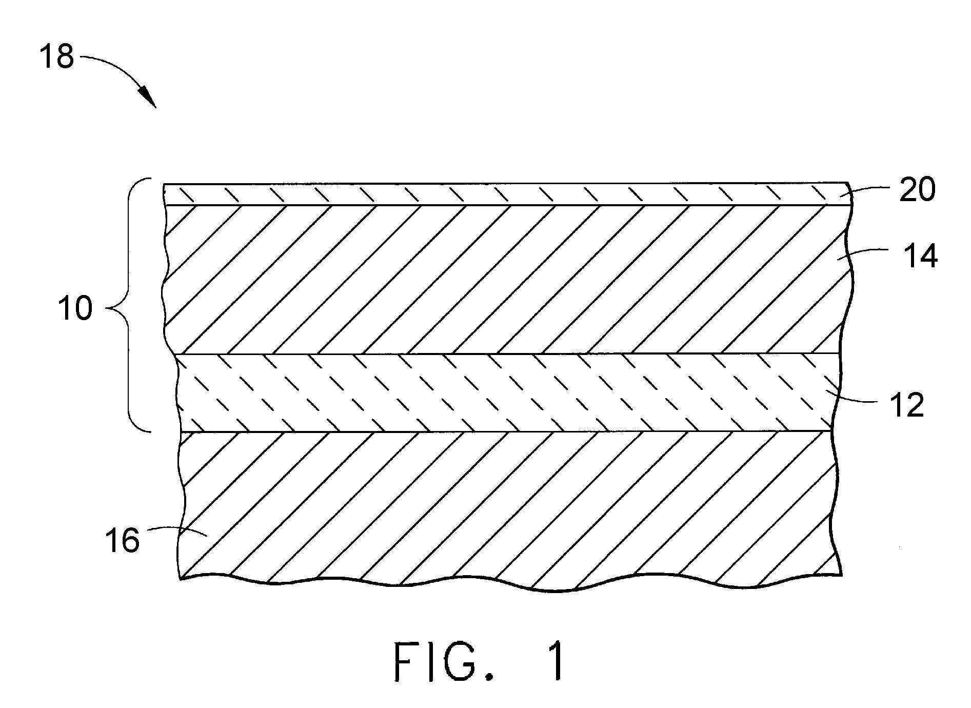
[0007]The coating system includes a metallic sacrificial undercoat on a surface of the component, and a ceramic topcoat deposited by thermal spray on the undercoat. The undercoat contains a metal or metal alloy that is more active in the galvanic series than iron, and electrically contacts the surface of the component. The ceramic topcoat consists essentially of a ceramic material chosen from the group consisting of mixtures of alumina and titania, mixtures of chromia and silica, mixtures of chromia and titania, mixtures of chromia, silica and titania, and mixtures of zirconia, titania and yttria. The coating system may optionally include a polymeric sealer to seal its surface, providing protection from ingress of corrosive agents and also improving the solid particle and water droplet erosion characteristics of the coating by virtue of its elastic nature.
[0009]A significant advantage of this invention is the ability of the coating system to provide both corrosion resistance and resistance to erosion by water droplet, thereby enhancing the corrosion pitting and crevice corrosion resistance of the protected surface, which in the case of a compressor blade has the potential for greatly extending the life of the blade. The coating system takes advantage of the fact that a sacrificial undercoat bonded to and electrically contacting the surface of a compressor blade will provide excellent corrosion resistance, while a hard topcoat will provide a shield against erosion by water impingement and thus reduce the incidence of pitting and crevice corrosion. The coating system can be strategically placed on a compressor blade, with the thickness of the coating tailored to provide the desired benefits while minimizing any loss in aerodynamic performance of the airfoil attributable to the coating system. Additional benefits of the coating system are believed to include the ability to enhance the blade anti-fouling capability and damage tolerance of a rotating blade.

Problems solved by technology

These systems generally entail introducing water droplets at the compressor inlet, with the result that the blades of the first stage of the compressor are impacted by water droplets at high velocities.
Compressor blades formed of iron-based alloys, including series 400 stainless steels, are prone to water droplet erosion at their leading edges, including their roots where the blade airfoil attaches to the blade platform.
The blades are also susceptible to corrosion pitting along the leading edge surfaces of the blades resulting from a build-up of fouling particles that cause galvanic attack.
Because compressor blades are under tremendous stress due to centrifugal forces and vibration, pits and crevices located at the blade roots can lead to high cycle fatigue (HCF) cracking and, if the blade is not removed, eventual loss of the blade.
While blades formed of nickel and titanium alloys are capable of exhibiting improved corrosion resistance, they do not necessarily exhibit improved resistance to water droplet erosion.

Method used


Image

  • Erosion and corrosion-resistant coating system and process therefor
  • Erosion and corrosion-resistant coating system and process therefor

Examples


Embodiment Construction

[0012]The present invention provides an erosion and corrosion-resistant coating system that is particularly well suited for protecting components formed of iron-based alloys, and particularly industrial gas turbine compressor blades that are formed of martensitic stainless steels and subjected to water droplet erosion and corrosion pitting. Notable examples include first stage compressor blades formed of series 400 martensitic stainless steels such as AISI 403 and proprietary formulations such as GTD-450 precipitation-hardened martensitic stainless steel. While the invention will be described in reference to compressor blades formed of a stainless steel, it should be understood that the teachings of this invention will apply to other components that are formed of a variety of iron-based alloys and benefit from improved resistance to water droplet erosion and corrosion pitting.

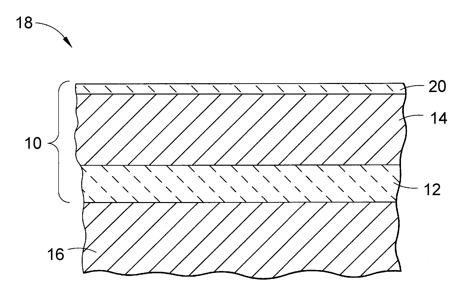
[0013]FIG. 1 schematically represents a coating system 10 of this invention as including a sacrificial under...


PUM

PropertyMeasurementUnit
Fractionaaaaaaaaaa
Fractionaaaaaaaaaa
Fractionaaaaaaaaaa

Abstract

A coating system and process capable of providing erosion and corrosion-resistance to a component, particularly a steel compressor blade of an industrial gas turbine. The coating system includes a metallic sacrificial undercoat on a surface of the component substrate, and a ceramic topcoat deposited by thermal spray on the undercoat. The undercoat contains a metal or metal alloy that is more active in the galvanic series than iron, and electrically contacts the surface of the substrate. The ceramic topcoat consists essentially of a ceramic material chosen from the group consisting of mixtures of alumina and titania, mixtures of chromia and silica, mixtures of chromia and titania, mixtures of chromia, silica, and titania, and mixtures of zirconia, titania, and yttria.

Description

BACKGROUND OF THE INVENTION[0001]The present invention generally relates to protective coatings and coating processes for turbine components. More particularly, the invention relates to a coating system suitable for use on steel compressor blades of a gas turbine to promote the water droplet erosion and corrosion resistance of the blades.[0002]On-line water wash, fogging, and evaporate cooler systems have been employed to improve the performance of compressors of large industrial gas turbines, such as those used by utilities to generate electricity. These systems generally entail introducing water droplets at the compressor inlet, with the result that the blades of the first stage of the compressor are impacted by water droplets at high velocities. Compressor blades formed of iron-based alloys, including series 400 stainless steels, are prone to water droplet erosion at their leading edges, including their roots where the blade airfoil attaches to the blade platform. The blades are ...

Claims


Application Information

Patent Timeline
IPC IPC(8): C23C4/10B32B15/04
CPCC23C4/02C23C4/105C23C4/18C23C28/00C23C30/00F01D5/288C23C28/347F05D2300/21C23C28/321C23C28/322C23C28/3225C23C28/345C23C28/3455F05D2260/95C23C4/11Y10T428/31678
Inventor PABLA, SURINDER SINGHSCHAEFFER, JON CONRADPAREEK, VINOD KUMARBUCCI, DAVID VINCENTMOORS, THOMASLIPKIN, JANE MARIE
Owner GENERAL ELECTRIC CO
Learn More