
Process for the conversion of biomass to liquid fuels and specialty chemicals

a technology of biomass and liquid fuel, applied in the direction of fuels, organic chemistry, combustion gas production, etc., can solve the problems of short life time, difficult operation, and high cost of the process

Active Publication Date: 2009-04-09
MARD INC
View PDF12 Cites 104 Cited by
  • Summary
  • Abstract
  • Description
  • Claims
  • Application Information

AI Technical Summary

Benefits of technology

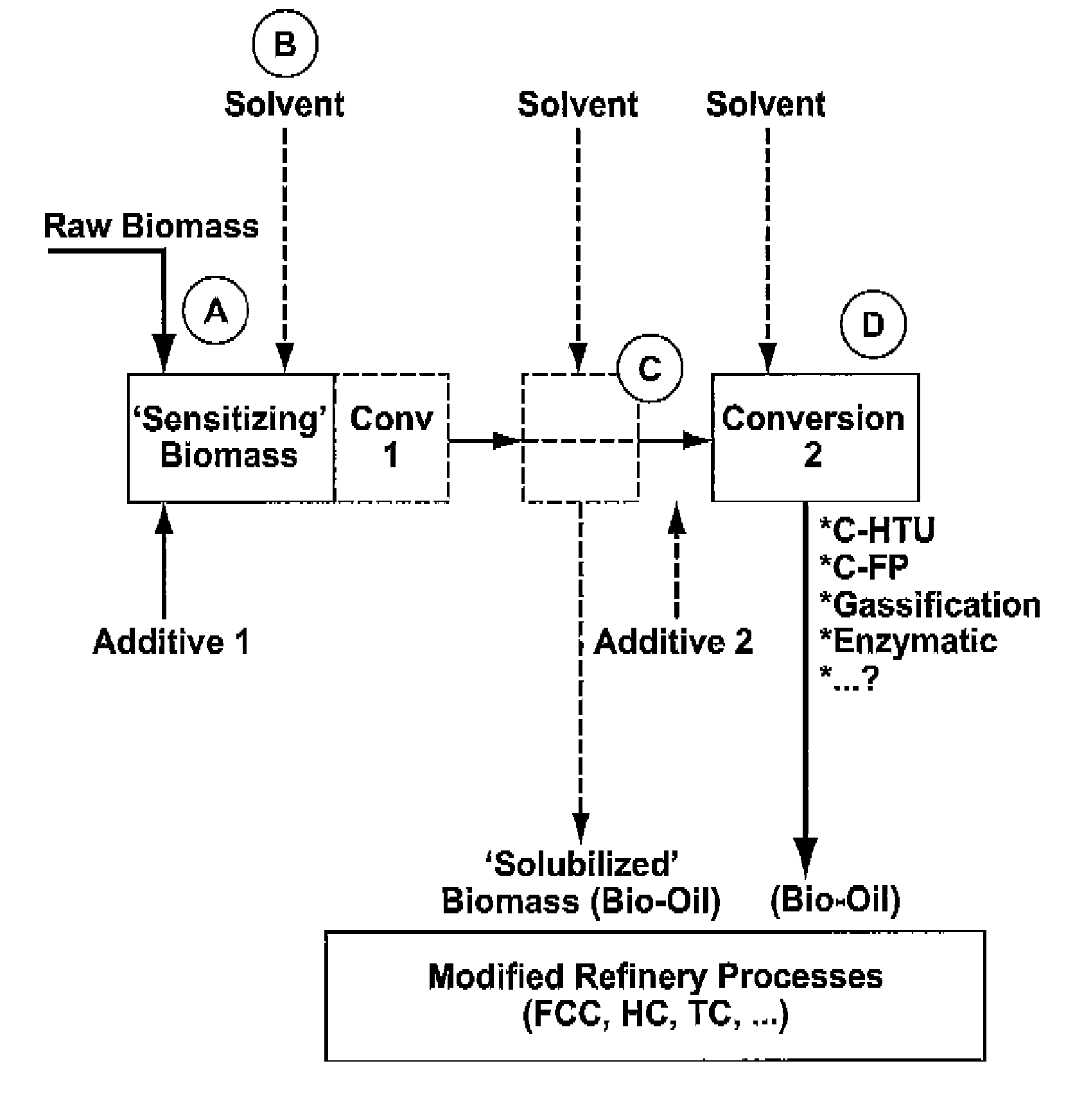
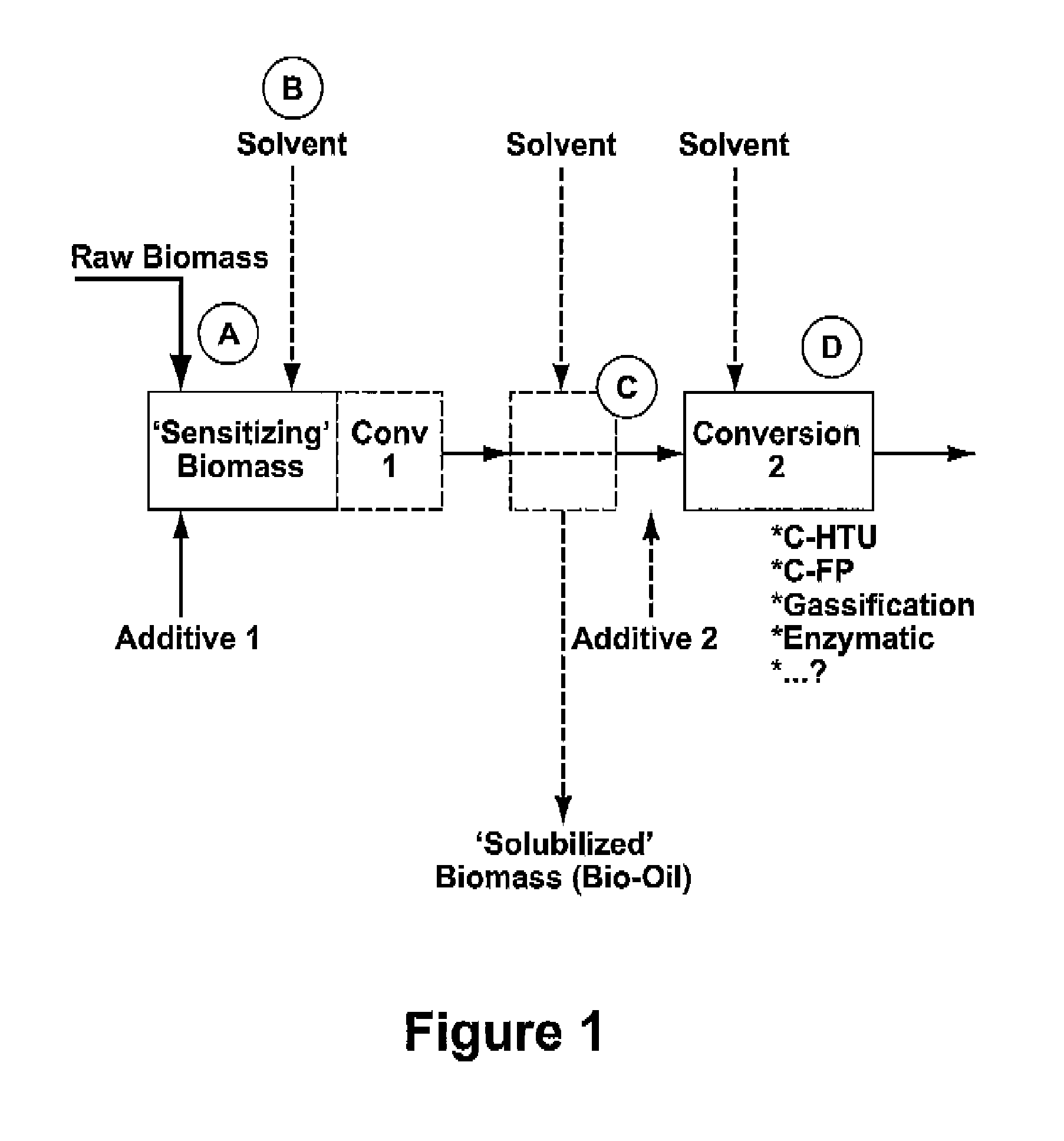
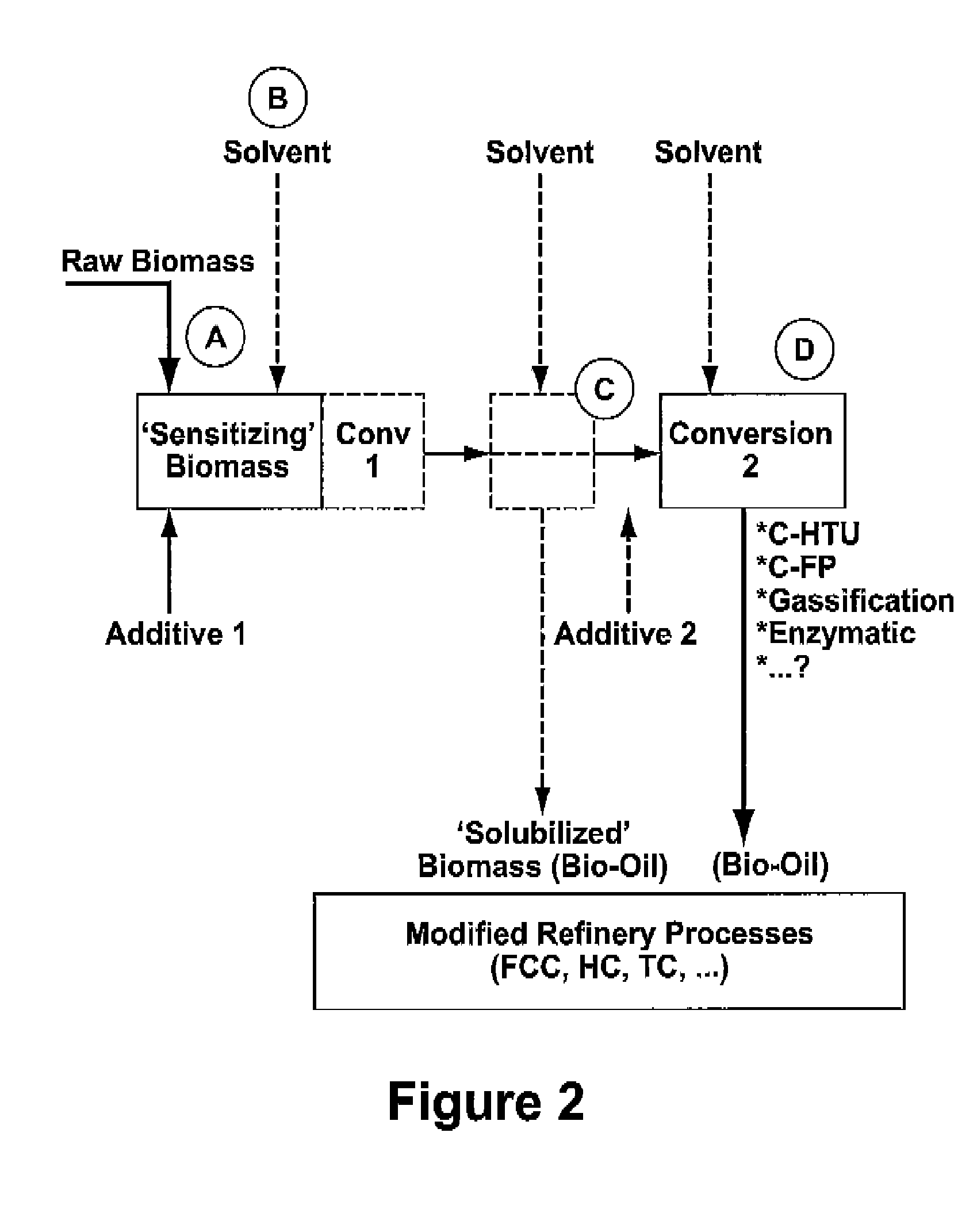
[0033]Due to the activation taking place in step a), optionally aided by the addition of a solvent (step b), step c) can be carried out under mild conditions. As a result the product obtained in step c) is not substantially degraded. Unconverted biomass from step c) is subsequently subjected to a second conversion in step d). Optionally, and preferably, converted biomass obtained in step c)

Problems solved by technology

The high temperatures and pressures that are needed to obtain suitable conversion rates make these processes expensive, requiring special high pressure equipment constructed with special metal alloys which for commercial plants, are difficult to operate and have relatively short life times. In addition, the products obtained in HTU processes are heavily degraded because of polymerization and coke formation that take place under the prevailing reaction conditions.
The liquid products obtained by HTU processes tend to be highly acidic and corrosive, and unstable.
The resulting liquid products are of poor quality, heavily degraded, and low pH, and require extensive (hydro-) treatment for upgrading to transportation fuels or chemical feedstocks.
Gasification of biomass, followed by FT synthesis, is inherently expensive as it involves a complete breakdown of hydrocarbon material, followed by a synthesis of different hydrocarbons.
This route involves a complex multi-step and therefore costly processing scheme.
The process is slow, requiring 24 hours or more per batch and operates best at low solid to liquid ratios.
The enzymes used in these processes are expensive when compared to the cost of chemicals used in chemical conversion processes.
Acid hydrolysis is carried out under atmospheric conditions and at temperatures below 100° C. The handling of large quantities of acid makes this process unattractive, in particular because the acid must be either removed or neutralized before the fermentation step.
The formed salts adversely affect the subsequent fermentation process.

Method used


Image

  • Process for the conversion of biomass to liquid fuels and specialty chemicals
  • Process for the conversion of biomass to liquid fuels and specialty chemicals
  • Process for the conversion of biomass to liquid fuels and specialty chemicals

Examples


example 1

[0131]Saw dust was prepared by repeatedly sawing through a piece of construction lumber with a circular saw. Judged by appearance the saw dust particles were predominantly rod-like in shape, and had a mean average larger particle dimension of about 1-2 mm, and a smaller particle dimension of about 0.5 mm.

[0132]Experiments were carried out in 2 mL glass test tubes, able to withstand pressures well in excess of 10 bar. The test tubes were provided with bakelite stoppers, which were equipped with pressure gauges for monitoring the pressure inside the test tubes. The test tubes were provided with magnetic stirrers, and heated in an oil bath. In all experiments the oil bath was kept at 180° C. The pressure inside the test tubes was 10 bar, corresponding with a temperature inside the tubes of 180° C.

[0133]Hydrotalcite (“HTC”) from Aldrich, which is magnesium aluminum hydroxycarbonate of the formula Mg6Al2(CO3)(OH)16. 4H2O, CAS number 11097-59-9, was calcined in air for 1 hour at 650° C.

[0...

example 2

[0141]Biomass material made from White Pine wood milled to an average particle size of 500 micrometers is dispersed in a solution containing Mg(NO3)2 and Al(NO3)3. The Mg / Al mole ratio for this solution is 3. The resulting slurry is stirred for thirty minutes to allow maximum penetration of the solution into the wood particles. The excess solution is drained off and the resulting wet biomass material re-slurried in sodium hydroxide solution such that the final pH is 9 to 10.

[0142]The resulting slurry is divided into two portions. The first portion is aged at 85° C. for six hours. The second portion is aged at 180° C. for one hour.

[0143]The resulting slurries are filtered and dried.

[0144]The presence of a mixture crystalline cellulose and HTC is confirmed by X-ray diffraction in both samples with the higher temperature treatment showing higher crystallinity.

[0145]Thermal decomposition of these samples is performed using a Mettler-Toledo TGA / SDTA851e thermo balance. The samples (10-15...

example 3

[0148]White Pine wood chips are initially pulverized with a mechanical mixer for 5 min to reduce the particle size to about 5 mm. This wood material is wet milled (15 wt % slurry based on weight of wood) along with raw natural magnesite powder (wood to magnesite ratio of 10:2) in a planetary high energy mill (Puverisette 6) for three hours. The slurry is dried at 100° C.

[0149]The presence of the inorganic phase, MgCO3 along with cellulose is confirmed by X-ray diffraction.

[0150]Using the same method described in Example 2 above, the weight loss for the dried wood sample treated with magnesite is about 5 to 10% higher than the untreated wood, while the decomposition of the wood starts at a lower temperature than the untreated wood.


PUM

PropertyMeasurementUnit
Angleaaaaaaaaaa
Temperatureaaaaaaaaaa
Pressureaaaaaaaaaa

Abstract

Disclosed is a hydrothermal treatment process for conversion of a carbon-based energy carrier material. The process comprises a step for sensitizing or activating the carbon based energy carrier material to increase its susceptibility to hydrothermal conversion. As a result of the sensitization step, the hydrothermal conversion step itself may be carried out under relatively mild conditions.The process comprises the steps of sensitizing the carbon-based energy carrier material to increase its susceptibility to hydrothermal conversion; and subjecting the sensitized carbon-based energy carrier material to hydrothermal conversion at a temperature of less than 300 degrees centigrade in a hydrothermal treatment reactor.

Description

BACKGROUND OF THE INVENTION[0001]1. Field of the Invention[0002]The present invention relates to the conversion of solid biomass to liquid fuels and specialty chemicals.[0003]It has long been recognized that biomass, in particular biomass of plant origin, is abundantly available and is a potential source of liquid fuels and valuable chemicals. See, for example, “Energy production from biomass”, by P. Mc.Kendry—Bioresource Technology 83 (2002) p 37-46, and “Coordinated development of leading biomass pretreatment technologies” by C. E. Wyman et al, Bioresource Technology 96 (2005) 1959-1966.[0004]Refined biomass materials, such as vegetable oils, starches, and sugars, can almost completely be converted to liquid fuels such as biodiesel (methyl or ethyl esters of fatty acids) and ethanol. However, the use of these refined biomass materials as starting points for liquid fuels diverts precious food resources from animal and even human consumption. This makes these starting materials expe...

Claims


Application Information

Patent Timeline
IPC IPC(8): C10L1/18C10J3/00C10G1/00C12P1/00
CPCC10G1/006C10G1/02C10G2300/4081C10G2300/4006C10G2300/1014Y02P30/20C10G1/04
Inventor O'CONNOR, PAULSTAMIRES, DENNISDAAMEN, SJOERD
Owner MARD INC
Learn More