
Polarizing plate and liquid crystal display device using the same

a technology of liquid crystal display device and polarizing plate, which is applied in the direction of instruments, polarising elements, optics, etc., can solve the problems of difficult to increase the birefringence index, liquid crystal display device has rapidly become large, and fails to meet the severe requirement, etc., to achieve excellent reworkability and high optical compensatory performance

Inactive Publication Date: 2009-04-02
FUJIFILM CORP
View PDF3 Cites 41 Cited by
  • Summary
  • Abstract
  • Description
  • Claims
  • Application Information

AI Technical Summary

Benefits of technology

The present invention provides a polarizing plate for a liquid crystal display device that has excellent optical compensatory performance and is easy to handle. The polarizing plate has a high degree of elasticity in the adhesive layer and protective films, which prevents leakage of light at the edges of the screen and ensures smooth operation of the display. The invention also provides a method for adjusting the modulus of elasticity of the adhesive layer and protective films to achieve optimal performance. The invention also includes a liquid crystal display device comprising the polarizing plate and a liquid crystal cell.

Problems solved by technology

With liquid crystal display devices for TV set use which are of a large size and expected to be viewed at various angles requirement for viewing angle dependence is so severe that even the above-mentioned technique fails to satisfy the severe requirement.
It is generally known that cellulose triacetate is a high molecular material which is so difficult to stretch that it is difficult to increase its birefringence index.
In recent years, however, liquid crystal display devices have rapidly become large-sized and, with it, there have arisen a problem of panel loss due to lamination failure upon laminating a polarizing plate onto a panel.
On the other hand, there has arisen a problem of leakage of light at the periphery of a screen upon black display due to shrinkage stress of a polarizing plate.
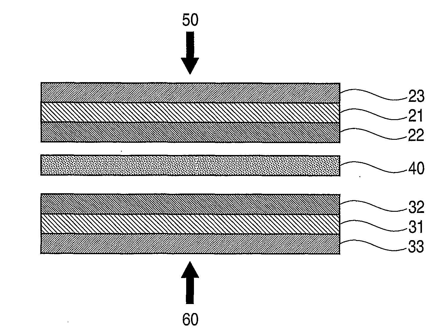
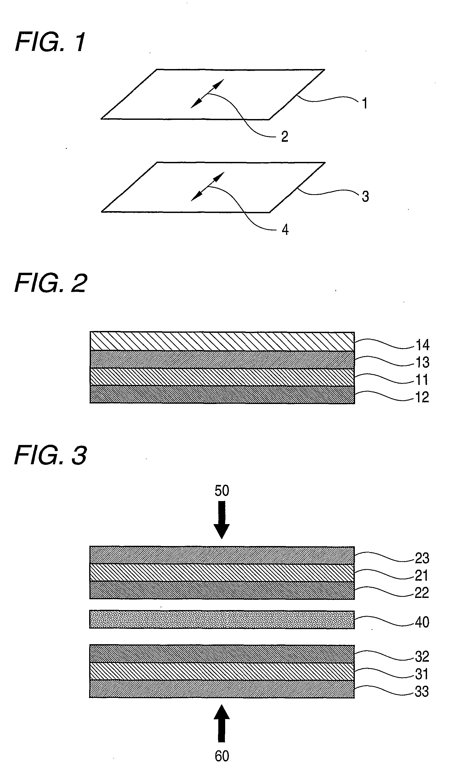
The polarizing plate tends to shrink due to change in environmental temperature and humidity but, since it is fixed to a liquid crystal cell by an adhesive layer, a stress is generated locally (particularly at the periphery of a screen) in the protective layer of the polarizing plate, the adhesive layer and the glass substrate of a liquid crystal cell, and leakage of light occurs due to change in birefringence based on photoelasticity of each of them.

Method used


Image

  • Polarizing plate and liquid crystal display device using the same
  • Polarizing plate and liquid crystal display device using the same
  • Polarizing plate and liquid crystal display device using the same

Examples


production example 1

Formation of a Cellulose Acylate Film Using a Band Casting Machine

Films 1 to 18

(1) Cellulose Acylate

[0453]Cellulose acylates having different kinds of acyl groups and different substitution degrees as shown in Table 1 were prepared. Acylation reaction was conducted by adding sulfuric acid (7.8 parts by mass per 100 parts by mass of cellulose) as a catalyst and carboxylic acids as a raw material for the acyl substituent and performing the reaction at 40° C. In this occasion, the kind of acyl group, total substitution degree and substitution degree at 6-position were controlled by adjusting the amount of the sulfuric acid catalyst, the amount of water and the ripening period. The ripening was conducted at 40° C. After the acylation, ripening was conducted at 40° C. Further, a low molecular component of the cellulose acylate was removed by washing with acetone.

[0454]Additionally, in the table, CAB is an abbreviation for cellulose acetate butyrate (cellulose ester derivative wherein the...

production example 2

Formation of a Cellulose Acylate Film

(Film 24) Using a Drum Casting Machine

(1) Dissolution

[0474]The following composition was placed in a mixing tank and stirred while heating to 30° C. to dissolve the components to thereby obtain a cellulose acetate solution.

(Formulation of cellulose acetate solution)(parts by mass)Inner LayerOuter LayerCellulose acetate (acetylation100100degree: 60.9%)Triphenyl hosphate (plasticizer)7.87.8Biphenyldiphenyl phosphate3.93.9(plasticizer)Methylene chloride (first solvent)293314Methanol (second solvent)71761-Butanol (third solvent)1.51.6Silica fine particles00.8(“AEROSIL R972” manufactured byNippon Aerosil K.K.)Retardation increasing agent (RP2)1.40

[0475]The above-described cellulose acylate had the substitution degrees as follows.

Substitution degree A: 2.87; Substitution degree B: 0;

Total substitution degree A+B: 2.87; Substitution degree at 6-position: 0.907; Substitution degree at 6-position / Total substitution degree: 0.316

Retardation Increasing Agen...

production example 3

Preparation of a Cyclic Polyolefin Biaxially Stretched Film

Film 25

[0479]“ZEONOR 1420R” (manufactured by Nippon Zeon K.K.; 100 μl thick) was stretched in the longitudinal direction with a stretch ratio of 30% at a delivery temperature of 140° C. and a film surface temperature of 130° C. Then, the film was stretched in the transverse direction with a stretch ratio of 40% at a delivery temperature of 140° C. and a film surface temperature of 130° C. using a tenter stretching machine. Both ends of the film were cut off before the winding section to adjust the width to 1500 mm, and the film was wound up as a roll film of 4000 m in length. Thus, a biaxially stretched film 25 was prepared. The thickness of the thus-obtained film 25 was 60 μm. With the thus-prepared film 25, Re590 value and Rth590 value at a wavelength of 590 nm were measured at 25° C. and 60% RH using a birefringence-measuring apparatus of KOBRA 21ADH (Ohji Measurement Co., Ltd.). In order to calculate Rth590 value, 1.51 w...


PUM

PropertyMeasurementUnit
widthaaaaaaaaaa
sizeaaaaaaaaaa
sizeaaaaaaaaaa

Abstract

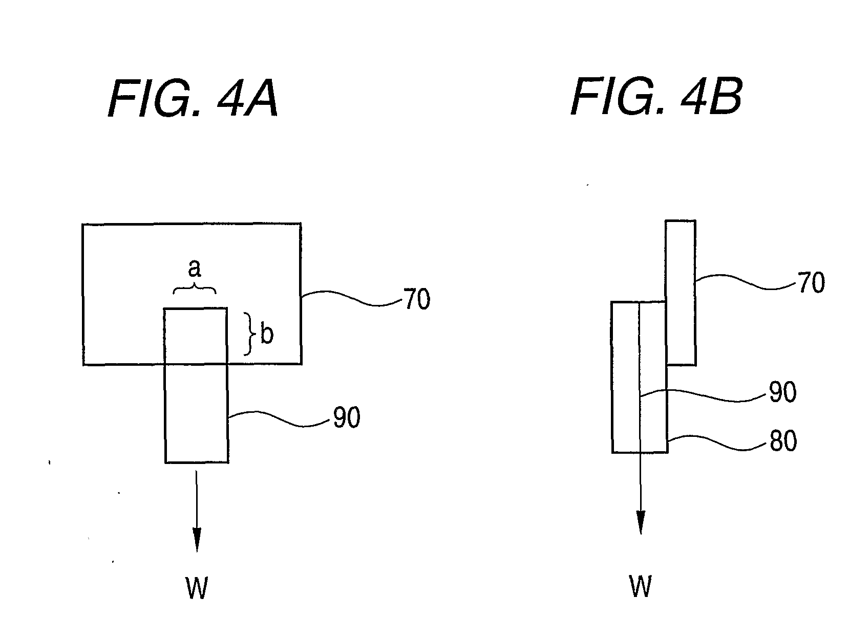
A polarizing plate comprising: a first protective film; a polarizer; and a second protective film, in this order, wherein at least one of the first protective film and the second protective film has an adhesive layer, and wherein the at least one of the first protective film and the second protective film has a modulus of elasticity E satisfying numerical formula (1), and the adhesive layer undergoes creep deformation of less than 70 μm when a piece of which having a size of 10 mm in width and 10 mm in length is stuck on an alkali-free glass plate and a load of 200 g is applied thereto in an atmosphere of 50° C. for 1 hour: numerical formula (1): 500 MPa≦E≦3000 MPa.

Description

TECHNICAL FIELD[0001]The present invention relates to a polarizing plate having a high optical compensatory performance and excellent reworkability and being so improved as to prevent leakage of light at the periphery of the screen generated by change in temperature and humidity or when a liquid crystal display device is in a state of being continuously switched on, and a liquid crystal display device using the same.BACKGROUND ART[0002]Liquid crystal display devices are widely used as monitors for personal computers or mobile devices and for TV sets due to their various advantages of being operable at a low voltage, consuming little power and permitting to reduce the thickness. As such liquid crystal display devices, there have been proposed liquid crystal display devices of various modes different from each other in the state of alignment of liquid crystal molecules within the liquid crystal cell. TN mode has so far been the main mode wherein molecules are aligned in a state of bei...

Claims


Application Information

Patent Timeline
Patent Type & Authority Applications(United States)
IPC IPC(8): G02F1/1335G02B5/30
CPCG02B1/105G02F1/133528G02B5/3033G02B1/14
Inventor OHGARU, IKUKOAMINAKA, EIICHIRO
Owner FUJIFILM CORP
Learn More