
Backup For Circuits Having Volatile States

a technology of circuits and currents, applied in emergency power supply arrangements, instruments, climate sustainability, etc., can solve problems such as power loss of peripheral circuits, and achieve the effects of preventing power loss from corrupting, reducing current consumption, and reducing leakag

Active Publication Date: 2009-02-12
MAXIM INTEGRATED PROD INC
View PDF0 Cites 16 Cited by
  • Summary
  • Abstract
  • Description
  • Claims
  • Application Information

AI Technical Summary

Benefits of technology

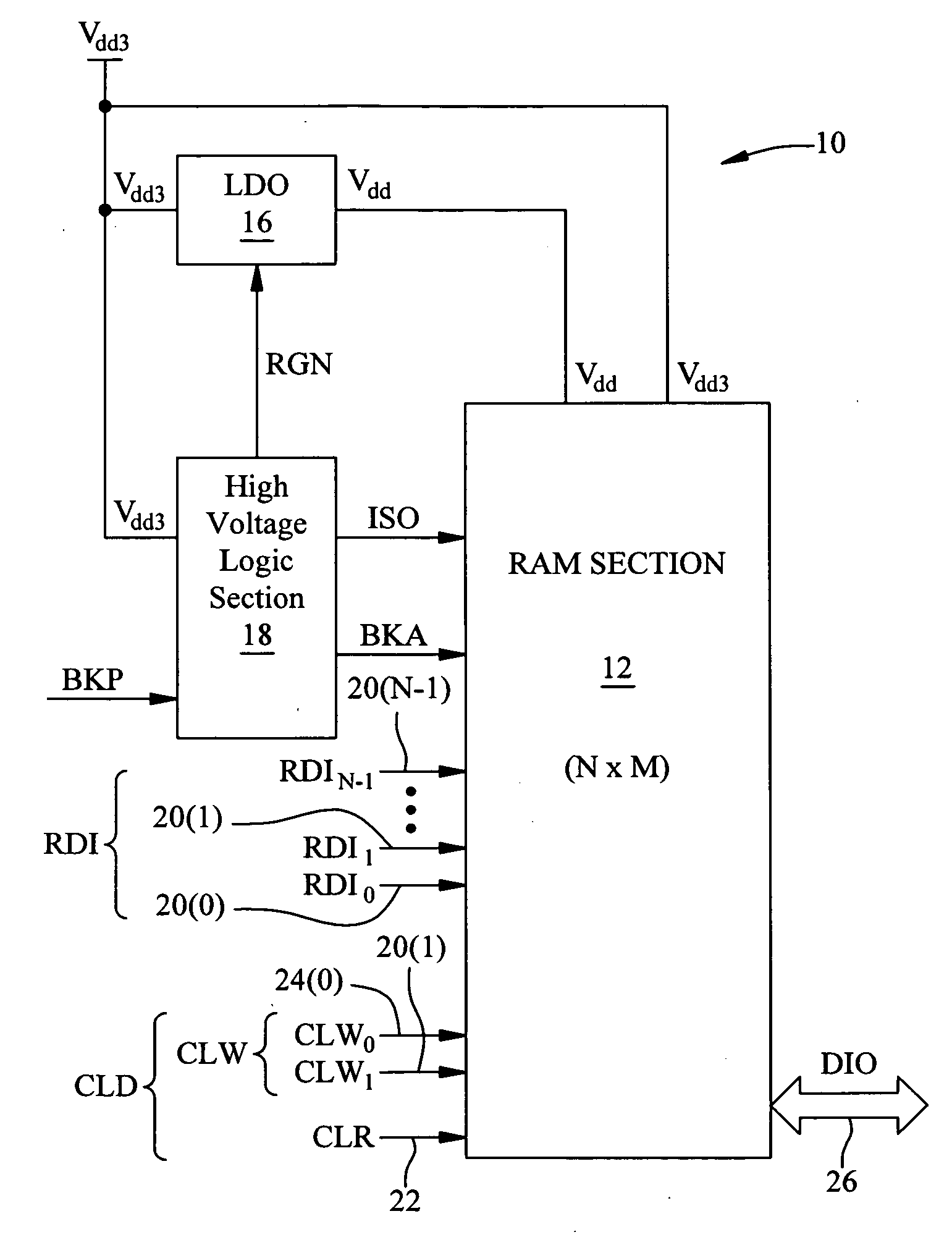
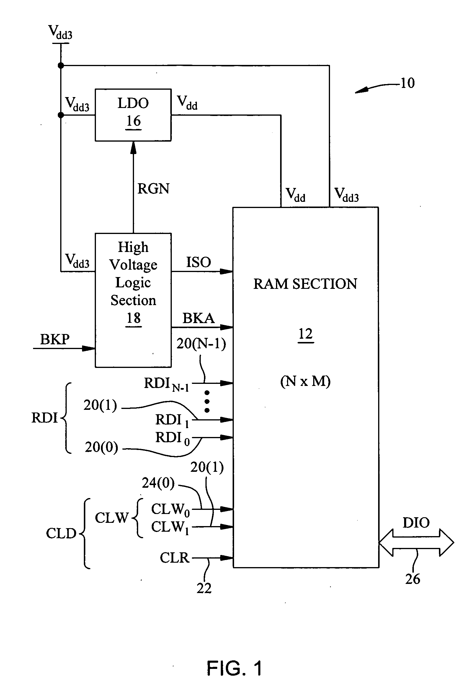
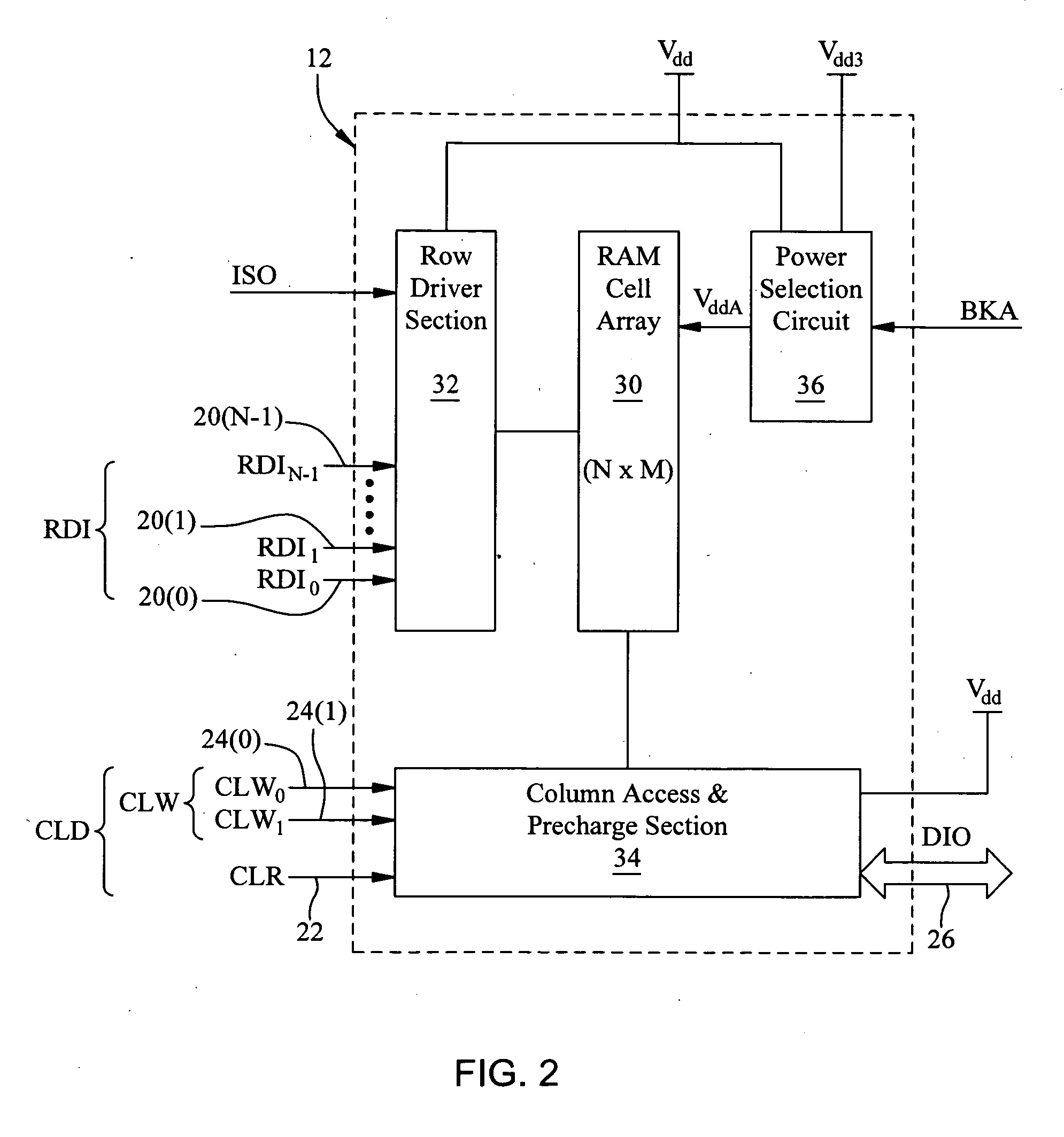
[0010]Thus, one of the key aspects of this disclosure is the deployment of high voltage memory cells, such as, for example, static RAM cells, in the memory core of the circuitry. Each memory cell is built of high voltage MOSFETs which may be powered by an unregulated voltage source, such as, for example, 3 volts ±10%, which has approximately two orders of magnitude less leakage for an equivalent device or element width as compared to a low voltage MOSFETs, for example, operating at 1.8 volts. This allows for the memory core power supply to be switched to a higher voltage when operating in the backup mode of operation so that the internal LDO, providing low voltage power during the normal mode of operation of the memory cells, may be powered-down or inactivated providing for additional savings in circuit current usage. An input backup signal selects whether the memory array power supply to be connected to the memory core is the low voltage or the high voltage, respectively, depending upon whether there is to be a normal mode of operation or a backup / standby mode of operation. In the backup or standby mode of operation, peripheral circuits of the memory circuit are inactivated because when the low voltage regulated supply is disenabled, these peripheral circuits will lose power. In order to prevent their power loss from corrupting the volatile data states in the memory core, an isolation signal is employed. In the normal mode of operation, the isolate signal is held at a first logic state, such as logic 0 (zero volts). Before power supplied to peripheral circuits is removed, the isolate signal is driven to logic 1 (higher voltage condition or Vdd3). This isolates the word lines to the memory cells, in particular, by turning on n-channel keeper devices that continually holds the memory word lines at a logic low thereby preventing access into the memory cells. Since the isolate signal and the memory array backup signal are high voltage signals, any circuitry that is engaged by these signals must also be high voltage circuitry.
[0011]While the high voltage memory cell has been discussed above, it will be realized by those skilled in the art that, as a backup memory element or cell formed from high voltage MOSFET transistors, for example, providing low current leakage, A MOSFET process can be available to provide a memory cell specifically for low current leakage and are not characterized as high voltage transistors. Therefore, it is important relative to this invention that in the characterization of the backup state retention circuit that the circuit contains elements that form a backup memory cell that is small in size, compared to other on-chip circuitry, and also may additionally provide lower current leakage.

Problems solved by technology

In the backup or standby mode of operation, peripheral circuits of the memory circuit are inactivated because when the low voltage regulated supply is disenabled, these peripheral circuits will lose power.

Method used


Image

  • Backup For Circuits Having Volatile States
  • Backup For Circuits Having Volatile States
  • Backup For Circuits Having Volatile States

Examples


Embodiment Construction

[0017]In the following description, for purpose of explanation, specific details are set forth in order to provide an understanding of the present invention. The present invention may, however, be practiced without some or all of these details. The embodiment of the present invention described below may be incorporated into a number of different electrical components, circuits, devices, and systems. Structures and devices shown in block diagram are illustrative of exemplary embodiments of the present invention and are not to be used as a pretext by which to obscure broad teachings of the present invention. Connections between components within the figures are not intended to be limited to direct connections. Rather, connections between components may be modified, re-formatted, or otherwise changed by intermediary components.

[0018]Reference in the specification to “one embodiment” or to “an embodiment” means that a particular feature, structure, characteristic, or function described ...


PUM


Abstract

An electrical circuit contains volatile states that are lost without continued application of power to circuit elements to preserve their volatile states. A first power source in the circuit provides power to the volatile state circuit for holding and preserving their volatile states. A power selection circuit is coupled to the circuit elements and has a plurality of selectable modes. A first mode of operation of the power selection circuit is selected when the circuit elements are to be operated at a first power level via the first power source which constitutes a first mode of operation. A second mode of operation is selected when the volatile state circuit elements are to be operated under a condition where the first power source is inactivated, such as, for example, during a circuit backup or standby operation. During the second mode of operation, the circuit elements volatile states are preserved via a power selection circuit that provides power from a second power source at a second power level, different from the first power level, to the volatile state circuit elements in place of the first power source.

Description

CROSS REFERENCE TO RELATED PATENT APPLICATIONS[0001]This application claims priority to U.S. provisional application Ser. No. 60 / 954,799, entitled “Low Leakage RAM Backup”, filed Aug. 8, 2007, which application is incorporated herein by reference in its entirety. This application is related to U.S. patent application, Ser. No. 12 / 188,622, filed on Aug. 8, 2008 and entitled, “Backup for Volatile State Retention in Absence of Primary Circuit Power”, and is incorporated here in its entirety by its reference.BACKGROUND[0002]A. Technical Field[0003]The present invention relates generally to digital circuit design, and more particularly, to the design of volatile circuits that contain volatile data states that may be lost without the continued application of applied power. An example of such a volatile circuits are digital memory circuits capable of retaining the data state of each memory cell during power-down periods in which the primary power source for the memory circuit is uncoupled ...

Claims


Application Information

Patent Timeline
Patent Type & Authority Applications(United States)
IPC IPC(8): H02J1/00
CPCH02J9/005Y04S20/20Y02B70/30
Inventor ZANDERS, GARY V.
Owner MAXIM INTEGRATED PROD INC
Learn More