
Exhaust gas purification device for internal combustion engine

a technology of exhaust gas purification device and internal combustion engine, which is applied in the direction of exhaust treatment electric control, electrical control, machines/engines, etc., can solve the problems of engine oil dilution, difficult to evaporate injection fuel, and increase the rotation speed of the engin

Inactive Publication Date: 2008-12-04
DENSO CORP
View PDF9 Cites 35 Cited by
  • Summary
  • Abstract
  • Description
  • Claims
  • Application Information

AI Technical Summary

Benefits of technology

[0008]It is an object of the present invention to provide an exhaust gas purification device of an internal combustion engine capable of achieving both of inhibition of oil dilution and inhibition of fuel consumption deterioration due to a post-injection.
[0011]With the configuration, the exhaust gas purification device can selectively use the first regeneration device, which causes the large oil dilution but the small fuel consumption deterioration, and the second regeneration device, which causes the small oil dilution but the large fuel consumption deterioration, based on the present oil dilution quantity in the engine. Thus, the exhaust purification device can inhibit the fuel consumption deterioration while controlling the oil dilution quantity to or under the predetermined value. That is, the exhaust gas purification device exerts an effect of achieving both of inhibition of the oil dilution and inhibition of deterioration of the fuel consumption during the DPF regeneration.
[0013]With the configuration, the exhaust gas purification device can have the two regeneration devices of the first regeneration device, which causes the large oil dilution but the small fuel consumption deterioration, and the second regeneration device, which causes the small oil dilution but the large fuel consumption deterioration, even without providing any specific external device. That is, the two kinds of the regeneration devices can be provided without necessitating an extra cost.
[0015]With the configuration, a quantity of the post-injection per one injection can be reduced even if the total post-injection quantity is the same. Thus, the quantity of the fuel adhering to the cylinder can be reduced and the oil dilution quantity can be reduced.
[0021]With the configuration, the oil dilution quantity can be derived accurately from the difference between the oil dilution quantity and the oil evaporation quantity.

Problems solved by technology

However, since the post-injection is performed during the expansion stroke, the injected fuel is hard to evaporate and tends to adhere to a wall surface of a cylinder.
The fuel adhering to the wall surface of the cylinder descends through a gap between a piston ring and the cylinder, causing a problem of engine oil dilution.
Furthermore, if the post-injection is repeatedly performed for a long time and the quantity of the fuel diluting the oil (referred to as an oil dilution quantity, hereinafter) becomes excessive, there is a possibility that lubrication of the piston is deteriorated or vaporized fuel enters an air intake side, causing a problem of increase in engine rotation speed.

Method used


Image

  • Exhaust gas purification device for internal combustion engine
  • Exhaust gas purification device for internal combustion engine
  • Exhaust gas purification device for internal combustion engine

Examples


Embodiment Construction

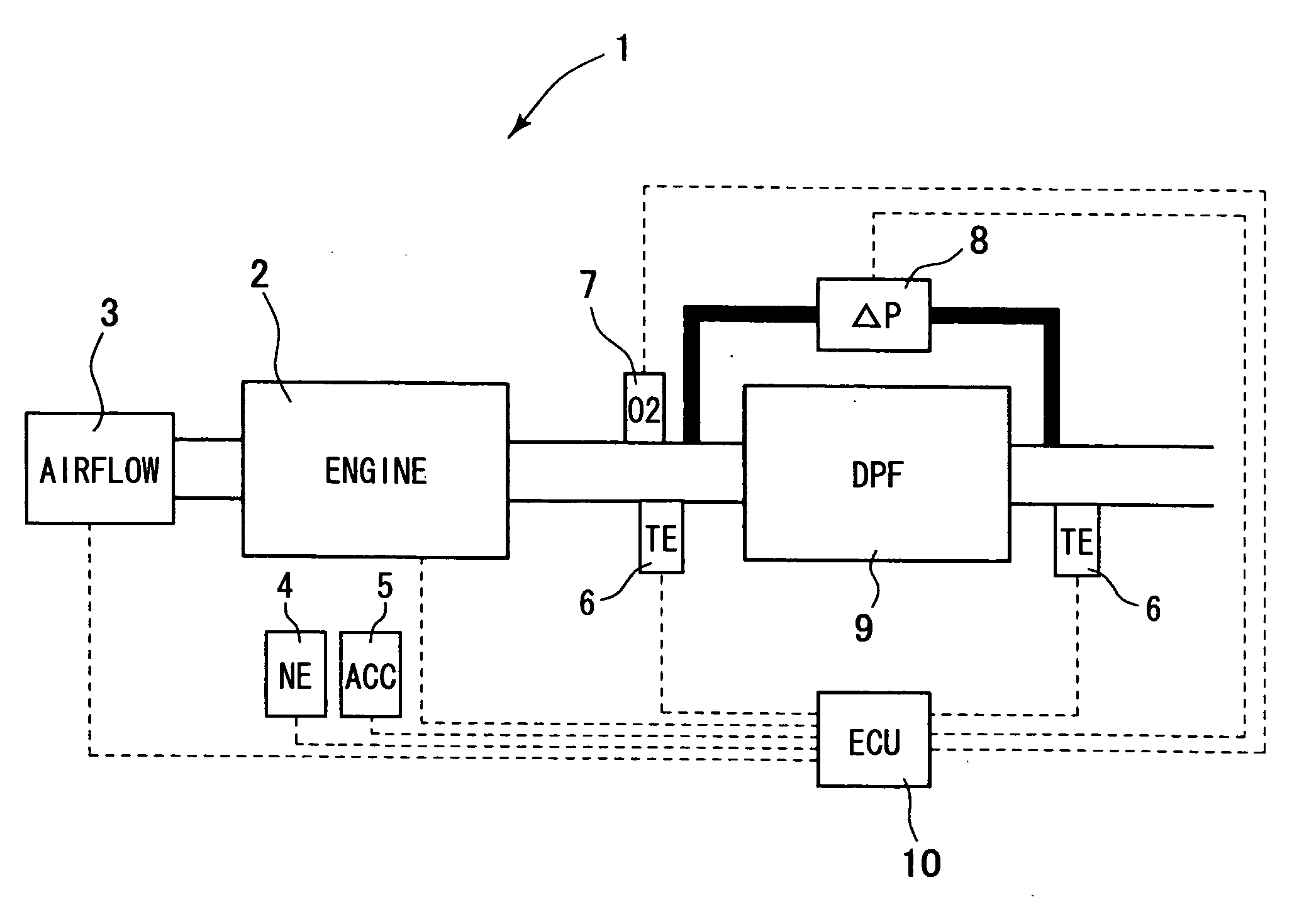
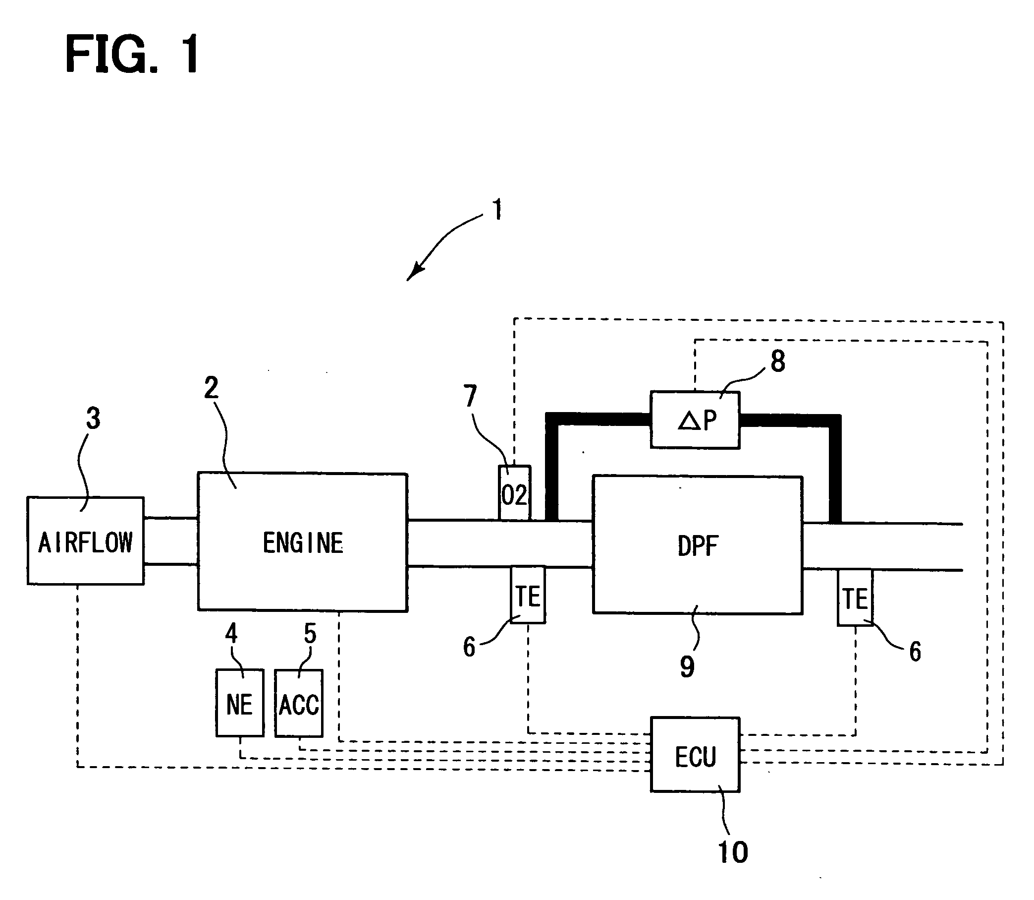
[0035]Now, a first embodiment of the present invention will be described with reference to drawings. FIG. 1 is a system diagram showing an exhaust gas purification device of an internal combustion engine 1 according to the present embodiment. A diesel engine 2 shown in FIG. 1 serves as a motor. An airflow meter 3 for measuring a flow rate of an air on an intake side of the diesel engine 2, an engine rotation sensor 4 for measuring rotation speed NE of the diesel engine 2, and an accelerator position sensor 5 for measuring a position ACC of an accelerator achieved by a driver are provided as sensors for determining a state of the diesel engine 2. The diesel engine 2 has an injector including a fuel injection valve for injecting fuel. The injector is electrically connected to an ECU 10 (engine control unit) as a control unit. The ECU 10 manages an opening degree and timing of the fuel injection valve of the injector for injecting the fuel. The airflow meter 3, the engine rotation sens...


PUM


Abstract

An exhaust gas purification device of a diesel engine having a DPF (diesel particulate filter) for collecting particulate matters such as soot and unburned components from exhaust gas of the diesel engine calculates an oil dilution quantity as a quantity of fuel diluting engine oil from a regeneration time of the DPF and an operation state. The exhaust gas purification device alleviates an increase in the oil dilution quantity by using a regeneration device that causes the oil dilution quantity less than the oil dilution quantity caused by another regeneration device when the oil dilution quantity exceeds a predetermined value. Thus, both of suppression of the oil dilution quantity and inhibition of deterioration of fuel consumption due to post-injection can be achieved.

Description

CROSS REFERENCE TO RELATED APPLICATION[0001]This application is based on and incorporates herein by reference Japanese Patent Application No. 2007-144844 filed on May 31, 2007.BACKGROUND OF THE INVENTION[0002]1. Field of the Invention[0003]The present invention relates to an exhaust gas purification device of an internal combustion engine having a diesel particulate filter (also referred to as a DPF) in an exhaust pipe for exhaust purification.[0004]2. Description of Related Art[0005]There is a conventional technology of a post-injection for sending additional fuel directly into a DPF in order to effectively combust particulate matters in the DPF by injecting the additional fuel in an expansion stroke after a main injection of an engine when a deposition quantity of the particulate matters in the DPF exceeds a predetermined value, for example, as described in Patent document 1 (Japanese Patent Application No. H08-42326) or Patent document 2 (Japanese Patent Application No. 2005-3077...

Claims


Application Information

Patent Timeline
IPC IPC(8): F01N9/00
CPCF01M1/18F01M2001/165F01N3/025F01N9/002F01N2430/06F02D41/029F02D41/402F02D41/405F02D2200/0812F02D2250/11Y02T10/44Y02T10/47Y02T10/40
Inventor KUBOSHIMA, TSUKASAYAHATA, SHIGETOSOGA, TSUTOMU
Owner DENSO CORP
Learn More