
Image processing method for determining motion vectors of interpolated picture and related apparatus

a technology of interpolation and image processing, applied in the field of image processing mechanism, can solve the problems of significant degraded quality of output images, image distortion in the interpolation regions rsub>inter/sub>′, etc., and achieve the effect of improving image quality and improving the conversion result of frame ra

Active Publication Date: 2014-07-08
MEDIATEK INC
View PDF10 Cites 4 Cited by
  • Summary
  • Abstract
  • Description
  • Claims
  • Application Information

AI Technical Summary

Benefits of technology

This method effectively determines target motion vectors for interpolated blocks, improving image quality and reducing distortion in frame rate conversion results.

Problems solved by technology

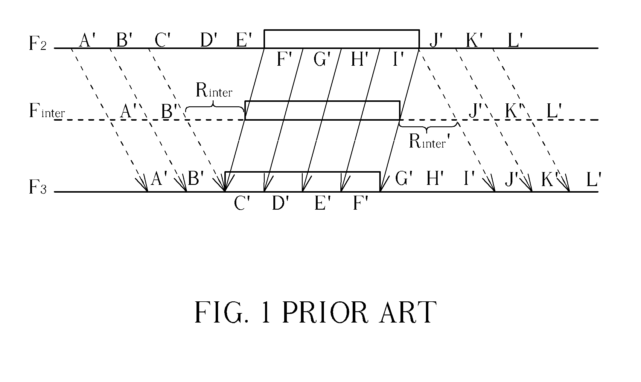
In fact, since the block matching algorithm cannot find background images C′, D′ (covered by a foreground object) in image picture F3 and, likewise, cannot find images H′, I′ (covered by a foreground object) in image picture F2, the block matching algorithm fails to determine motion vectors as normal, leading to an image distortion in the interpolated regions Rinter and Rinter′.
When applied to a frame rate conversion, the conventional image interpolation mechanism degrades quality of output images by a significant amount.

Method used


Image

  • Image processing method for determining motion vectors of interpolated picture and related apparatus
  • Image processing method for determining motion vectors of interpolated picture and related apparatus
  • Image processing method for determining motion vectors of interpolated picture and related apparatus

Examples


Embodiment Construction

[0022]For ease of reading, the following describes those background image areas which are not blocked by a foreground object in a previous picture but blocked by a foreground object in a next picture as covered areas, whereas those background image areas which are blocked by a foreground object in a previous picture but not blocked by a foreground object in a next picture as uncovered areas; for example, the background image areas C′, D′, E′ shown in FIG. 1 are covered areas while the background image areas G′, H′, I′ are uncovered areas; it should be noted that the definitions described above are only for ease of explanation, and are not meant to limit the present invention.

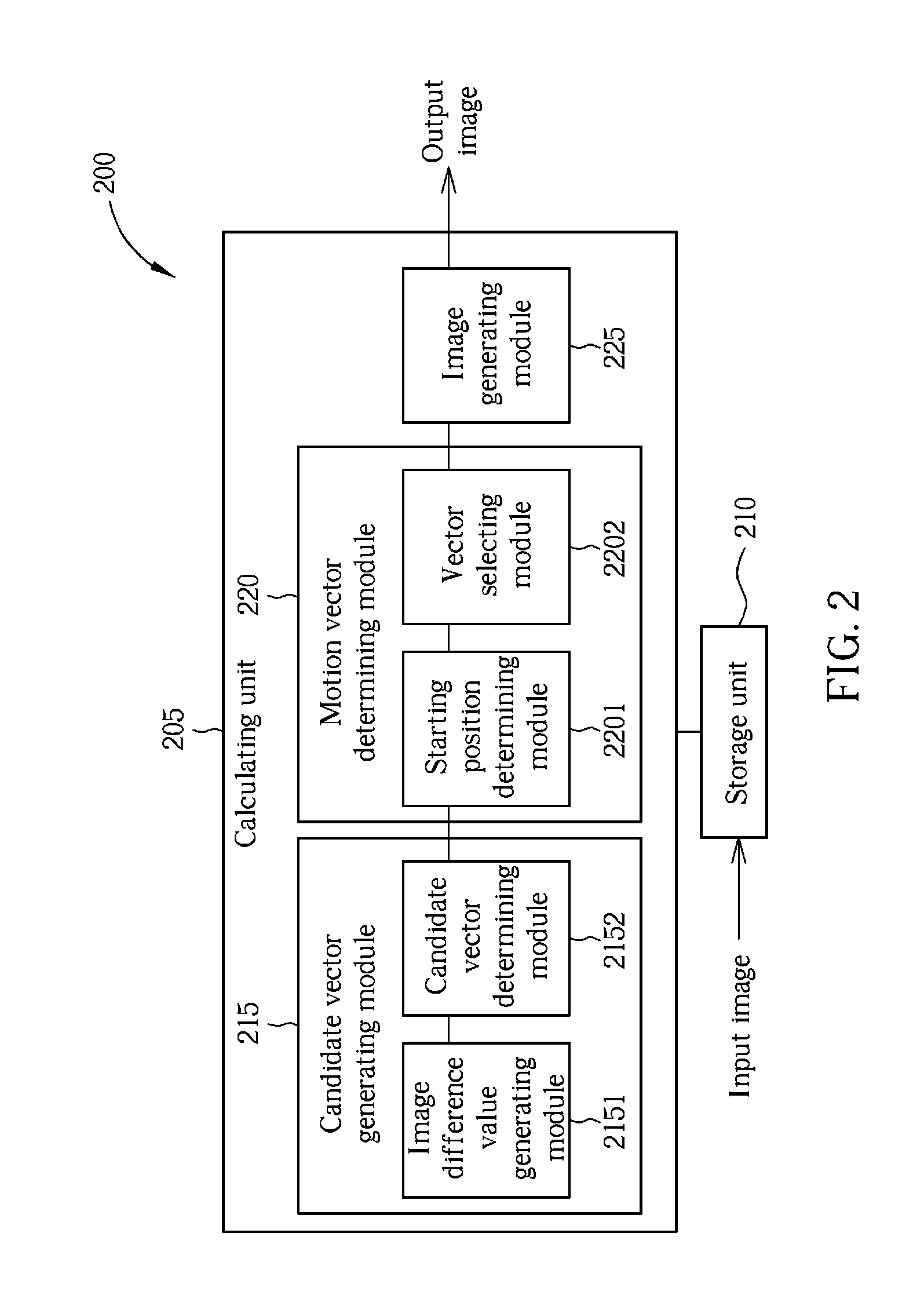
[0023]Please refer to FIG. 2 and FIG. 3A. FIG. 2 illustrates an image processing apparatus 200 according to a first embodiment of the present invention, and FIG. 3A illustrates a flowchart of operation of the image processing apparatus 200 shown in FIG. 2. For ease of explanation, the following describes the ope...


PUM


Abstract

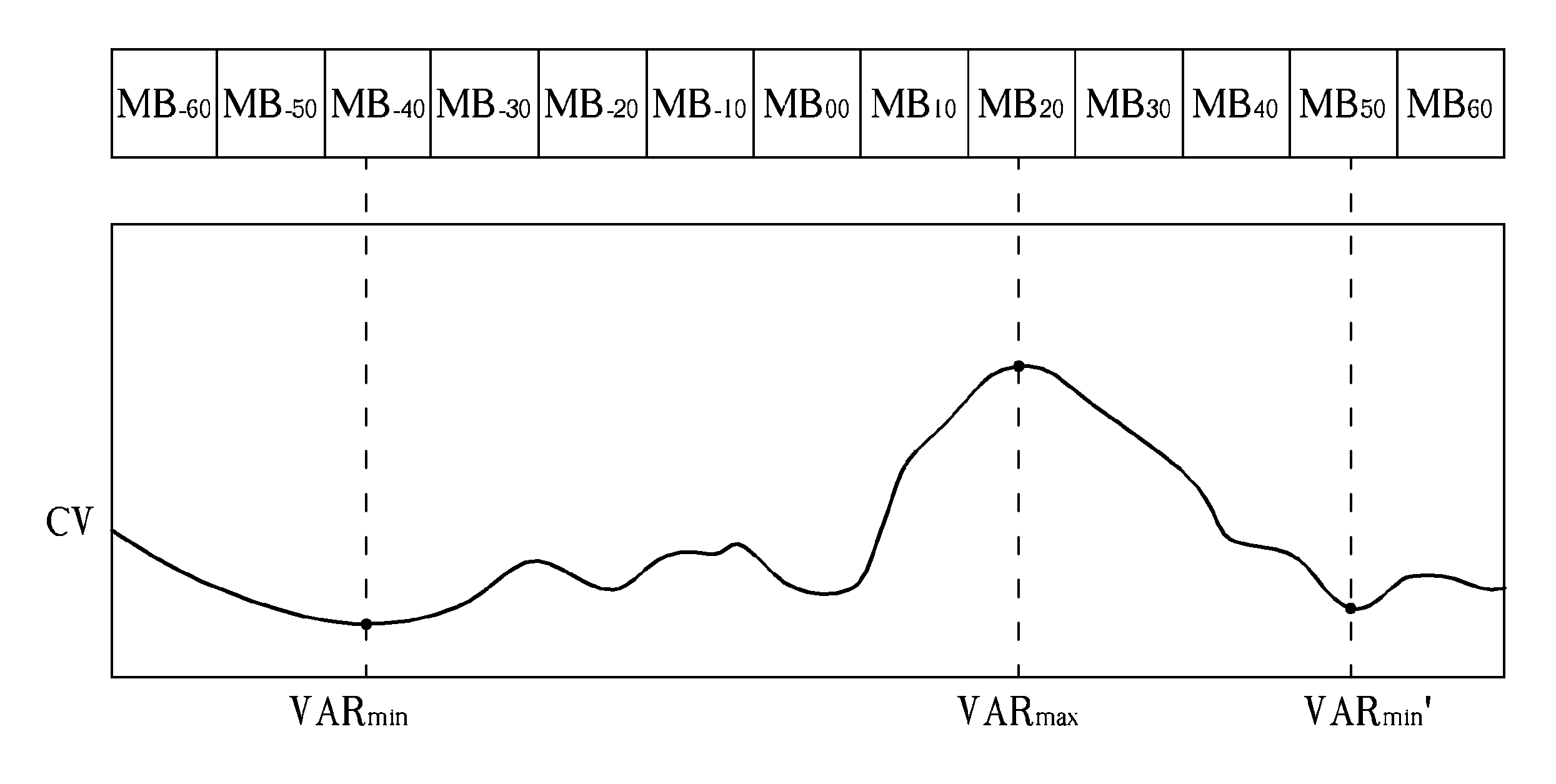
An image processing method for determining a motion vector of an interpolated block in a covered / uncovered area of an interpolated picture. The method comprises determining image difference values of successive blocks according to original motion vectors of the successive blocks; determining first and second motion vectors for the successive blocks according to the image difference values, wherein the first and the second motion vector of one of the successive blocks are the original motion vectors of two blocks located in both side of a block having a maximum image difference value; determining a starting point of the interpolated block according to the first and the second motion vectors of the successive blocks; and selecting one of the first and the second motion vectors of the interpolated block as the motion vector of the interpolated block according to the starting point and a starting point in a previous interpolated picture.

Description

BACKGROUND OF THE INVENTION[0001]1. Field of the Invention[0002]The present invention relates to an image processing mechanism, and more particularly, to an image processing method for determining a motion vector of an interpolated block, and a related apparatus.[0003]2. Description of the Prior Art[0004]In a conventional image interpolation mechanism, a motion vector of an interpolated block in an interpolated picture is directly determined according to a calculated result of a block matching algorithm and thereby an image of the interpolated block is generated according to the motion vector. Please refer to FIG. 1. FIG. 1 is a diagram illustrating an operation of the conventional block matching algorithm. As shown in FIG. 1, image pictures F2, F3 are sequential pictures of input images, an image picture Finter is an interpolated picture generated from the conventional image interpolation mechanism and A′˜L′ are background images of image pictures F2, F3, where each dotted-line arr...

Claims


Application Information

Patent Timeline
Patent Type & Authority Patents(United States)
IPC IPC(8): H04N19/00H04N5/14H04N9/64H04N11/02H04N11/04
CPCH04N19/00H04N5/145H04N7/0127H04N7/014
Inventor LIN, YU-SENHSU, TE-WEICHEN, CHUNG-YI
Owner MEDIATEK INC
Learn More