
Wiring Board and Wiring Board Manufacturing Method

Inactive Publication Date: 2008-11-27
NGK SPARK PLUG CO LTD
View PDF26 Cites 34 Cited by
  • Summary
  • Abstract
  • Description
  • Claims
  • Application Information

AI Technical Summary

Benefits of technology

[0013]An object of the present invention is to provide a wiring board manufacturing method capable of manufacturing a wiring board having a structure in which a ceramic dielectric layer and a polymer dielectric layer are composite laminated, with ease, and a wiring board manufactured by that method and capable of increasing the adhering strength between layers while being hard to cause a problem such as peeling at the time of reflow process or the like.
[0014]Another object of the present invention is to provide a wiring board which is structured to be able to prevent, in a wiring board having a built-in capacitor, the capacitor from being exposed at the end surface of the package and be hard to cause shortage between layers while being high in the reliability by making an external end surface of a ceramic dielectric layer constituting a capacitor withdraw from an end surface of a package and by making an external end surface of an electrode of the capacitor further withdraw from the external end surface of the ceramic dielectric layer.

Problems solved by technology

Since in an integrated circuit device such as CPU and other LSI that operates at high speed, power source wires branching off from a common power source are allotted to a plurality of circuit blocks within an integrated circuit, there is a problem that when a number of elements within the circuit blocks perform high-speed switching at the same time, large current is drawn from the power source at one time and a resulting variation in the power source voltage will become a kind of noise, which noise is transmitted to the respective circuit blocks through the power source wires.
In the meantime, in case of a large-scale integrated circuit such as CPU, the number of circuit blocks formed therein is large and there is a tendency that the number of power source terminals and ground terminals increases, so that the distance between the terminals is decreasing more and more.
A decoupling capacitor needs to be connected to each power source wire extending toward each circuit block, so that it is not only difficult from a point of view of a mounting technology but it goes against a miniaturizing trend or the like to connect capacitors separately to an integrated circuit having a number of densely arranged terminals.
Further, there is such a problem that the inductance of a terminal portion, when increased, is combined with a capacity component of a decoupling capacitor to cause a resonance point, thus making smaller the band width where a sufficient impedance reduction effect is obtained.
However, in the above-described patent document 1, there is provided a structure in which a capacitor is installed on an intermediate board interposed between an electronic part and a wiring board, thus causing a problem that the working time necessitated for installation of the electronic part on the wiring board is increased for the interposition of the intermediate board and it becomes difficult to make the assembly of the wiring board and the electronic part be lower in height.
This makes it possible to realize decrease in the height of the assembly but the following problem arises.
Namely, the adhering strength between the build-up layer and the capacitor portion is liable to decrease, particularly when a thermal cycle such as a reflow process for flip-chip connection of an electronic part is applied to the build-up layer and the capacitor portion, the thermal shear stress level between the layers due to the difference in the line expansion coefficient between the build-up layer and the high inductive ceramic layer becomes higher, thus being liable to cause a problem of peeling or the like.
Further, the capacitor using a thin layer of high inductive ceramic is difficult in handing at the time of connection to the build-up layer for wiring, thus causing a problem of a low manufacturing efficiency.
Further, by the prior technology, there is caused the following problems since the capacity to be formed is increased by forming the capacitor at an area that is determined as wide as possible with respect to the size of the external shape of a single unit (package) of wiring board but the capacitor portions are cut at the time of dicing if the single unit of wiring board and the capacitor have the same size.
(1) If an electrode made of metal such as Cu is exposed at an end surface of a package after dicing, oxidation-corrosion of the electrode is caused.
(2) The adherence at the interface between an electrode and a ceramic dielectric layer is weaker as compared with that between polymeric materials, thus possibly causing interlayer peeling due to shearing stress at the time of dicing and an intrusion path for intake of moisture thereafter.
(3) Sagging of an electrode made of metal such as Cu is liable to occur at the time of dicing, and shortage occurs between the layers.
(4) As compared with a single polymeric substance, an electrode made of metal such as Cu, particularly a ceramic dielectric layer made of high dielectric such as titanic acid barium increases the load at the time of dicing and accelerates wear and chipping of a blade.
In case such a structure is employed, the following problems arise.
One problem is that treatment liquid used for forming a capacitor on the first side causes an influence on elements on the second side.
Particularly, desmear treatment liquid used for removing residue at via holes causes a problem since it corrodes a polymeric material.
However, such a theory cannot be used in case a capacitor having a ceramic dielectric layer is formed only on one side of a core board portion.
This fact means that it is difficult to form plating layers of a uniform thickness and a uniform quality on the first and second sides.
Another problem is that the first and second sides become unequal in the mechanical characteristics depending upon whether they are formed with a capacitor.
This fact means that a defect such as bending or peeling is liable to be caused after a thermal history.

Method used


Image

  • Wiring Board and Wiring Board Manufacturing Method
  • Wiring Board and Wiring Board Manufacturing Method
  • Wiring Board and Wiring Board Manufacturing Method

Examples


Embodiment Construction

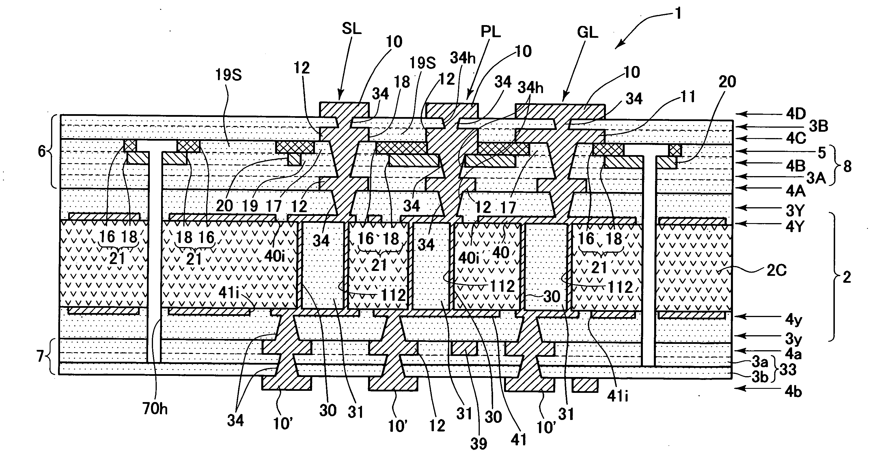
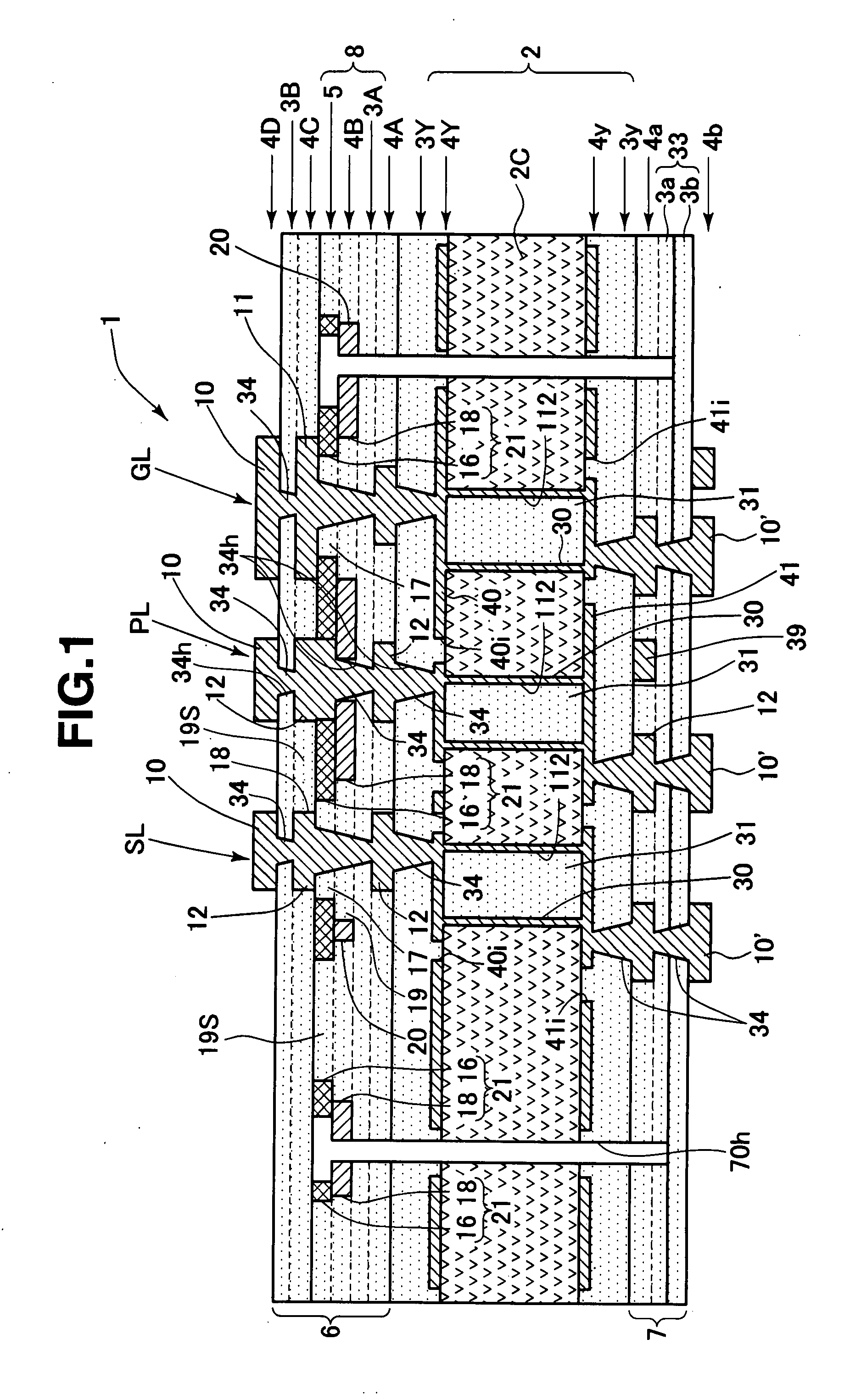
[0061]Hereinafter, an embodiment of the present invention will be described with reference to the drawings. FIG. 1 schematically shows a sectional structure of a wiring board 1 according to an embodiment of the present invention. The wiring board 1 is formed with, on both surfaces of a plate-shaped core 2c formed from a heat-resistant resin plate (e.g., Bismaleimide-Triazine resin), fiber-reinforced resin plate (e.g., glass fiber-reinforced epoxy resin) or the like, core conductor layers 4Y, 4y constituting wiring metal layers of predetermined patterns, respectively. The core conductor layers 4Y, 4y are formed into plane conductor patterns covering almost all of the surfaces of the plate-shaped core 2c and used as a power source layer (41 in the drawing) or a grounding layer (40 in the drawing). On the other hand, the plated-shaped core 2c is formed with through holes 112 by a drill or the like, and on the inner wall surfaces of the through holes are formed through hole conductors 3...


PUM

PropertyMeasurementUnit
Thicknessaaaaaaaaaa
Thicknessaaaaaaaaaa
Thicknessaaaaaaaaaa

Abstract

A wiring board including a stacked wiring layer portion in which a dielectric layer and a conductor layer are stacked is formed on a core board portion, the stacked wiring layer portion including a stacked composite layer portion in which a polymer dielectric layer, a conductor layer and a ceramic dielectric layer are stacked in this order, the conductor layer being partially cut in the in-plane direction so as to have a conductor side cut portion, the ceramic dielectric layer being partially cut in the in-plane direction so as to have a ceramic side cut portion, the ceramic side cut portion and the conductor side cut portion being communicated to form a communication cut portion, a polymer constituting the polymer dielectric layer being filled in the communication cut portion so as to extend through the conductor side cut portion to the ceramic side cut portion.

Description

TECHNICAL FIELD[0001]The present invention relates to a wiring board and a wiring board manufacturing method.BACKGROUND TECHNIQUE[0002]Patent Document 1: Unexamined Japanese Patent Publication No. 2003-142624[0003]Since in an integrated circuit device such as CPU and other LSI that operates at high speed, power source wires branching off from a common power source are allotted to a plurality of circuit blocks within an integrated circuit, there is a problem that when a number of elements within the circuit blocks perform high-speed switching at the same time, large current is drawn from the power source at one time and a resulting variation in the power source voltage will become a kind of noise, which noise is transmitted to the respective circuit blocks through the power source wires. Thus, from a point of view of inhibiting transmission of noise between the blocks due to the power source variation, it is effective to provide each circuit block with a decoupling capacitor for lowe...

Claims


Application Information

Patent Timeline
IPC IPC(8): H05K1/18H05K3/36
CPCH01L23/49822Y10T29/49126H01L23/50H01L2924/15787H01L2924/3011H05K1/0271H05K1/162H05K3/4602H05K2201/0187H05K2201/096H05K2203/016H05K2203/0537H01L2924/0002H01L23/49827H01L2924/00H05K3/46
Inventor YURI, SHINJIORIGUCHI, MAKOTOINUI, YASUHIKOOTSUKA, JUN
Owner NGK SPARK PLUG CO LTD
Learn More