
Method of forming an oxide coating with dimples on its surface

a technology of oxide coating and dimples, which is applied in the direction of coating, ion implantation coating, metallic material coating process, etc., can solve the problems of reducing the production cost of ethanol, reducing the production cost, and reducing the manufacturing cost. , to achieve the effect of reducing the manufacturing cos

Inactive Publication Date: 2008-10-09
NIE XUEYUAN +1
View PDF7 Cites 19 Cited by
  • Summary
  • Abstract
  • Description
  • Claims
  • Application Information

AI Technical Summary

Benefits of technology

[0011]Step 2. The etched metallic matrix surface then grows with the formation of a thin oxide layer by plasma oxidation when the applied voltage increases, making the surface smoother. The surface consists of corresponding metal-containing oxides on the metallic matrix areas and precipitating element-containing oxides in the grain boundary regions of the precipitates where metallurgical-bonding interfaces between the metallic matrix and grains of the precipitates are established. With the increase of the oxide layer thickness, the regions at hard precipitates will also perform plasma oxidation, forming oxides on their surfaces. The oxide coating layer thickness can be in the range of 0.5 to 5 microns and the surface roughness R.sub.a less than 0.6 micron. The dielectric plasma discharges on the oxide surface are utilized to produce a number of surface dimples with a size of 0.5 to 5 microns in diameter. The coverage of the dimples is more than 5,000 dimples per square millimeter. Such dimples can be used as oil reservoirs facilitating distribution of the oil lubricants for tribological applications.
[0013]Usually, the process should terminate at Step 2 in which the oxide layer with dimples on its surface has a thickness of 0.5 to 5 microns, and the surface roughness is less than 0.6 microns. There is no need for any post-treatments, polishing, honing, and cross-hatching, which reduces the manufacturing cost.
[0014]If the process ends at Step 3, the oxide layer thickness is in the range of 6 to 10 microns and surface roughness R.sub.a 0.8 to 1.5 microns. Although a slight surface polishing is usually suggested to make the surface finish from R.sub.a 0.8 to 1.5 microns to R.sub.a 0.3 to 0.5 micron for a tribological application, no grinding, honing, and crosshatching process are required, which can still significantly reduce the manufacturing cost.
[0015]The thin oxide coating formed on an Al—Si alloy can be applied on a sleeveless Al engine bore and piston for protection from mild and severe engine wear.
[0016]The thin oxide coating formed on an Mg alloy can be applied on a sleeveless Mg engine bore and piston for battling mild and severe engine wear.
[0017]The thin oxide coating has a dense ceramic underlayer which can provide corrosion prevention for Al, Mg, and Ti alloys.

Problems solved by technology

However, the sliding wear problem on the Al and Mg cylinder bores has to be dissolved before sleeveless Al and Mg engines are in use.
Unfortunately, the ethanol is corrosive to Al—Si alloys and Mg alloys.
Thick Cr-based, Ni-based, and oxide coatings may be some of the solutions, but those coating processes need pro-surface preparation and post-surface finish, i.e., honing and cross-hatching, which results in an extra cost.
Many coating processes have been eliminated from automotive applications due to the increased process cost.
The potential environmental pollution caused by the coating processes is also concerned.
Al and Mg parts usually suffer from corrosion problems, including general corrosion and galvanic corrosion caused by corrosive environment, deicing salts, and coolants.
Joining of those materials by welding, bolting, riveting, and adhesive bonding is subjected to galvanic corrosion.
A complicated grinding, polishing or honing post-process is necessary if the coating is used for tribological applications.
Such a high hardness usually causes severe wear to counterface materials during a sliding contact.
In addition, the processing time for the thick coating usually is very long, lasting 1 to 2 hours.
Those make the process expensive, limiting its general applications in corrosion prevention.
The relatively soft oxide coating will cause a little wear to the counterface materials.

Method used


Image

  • Method of forming an oxide coating with dimples on its surface
  • Method of forming an oxide coating with dimples on its surface
  • Method of forming an oxide coating with dimples on its surface

Examples


example 1

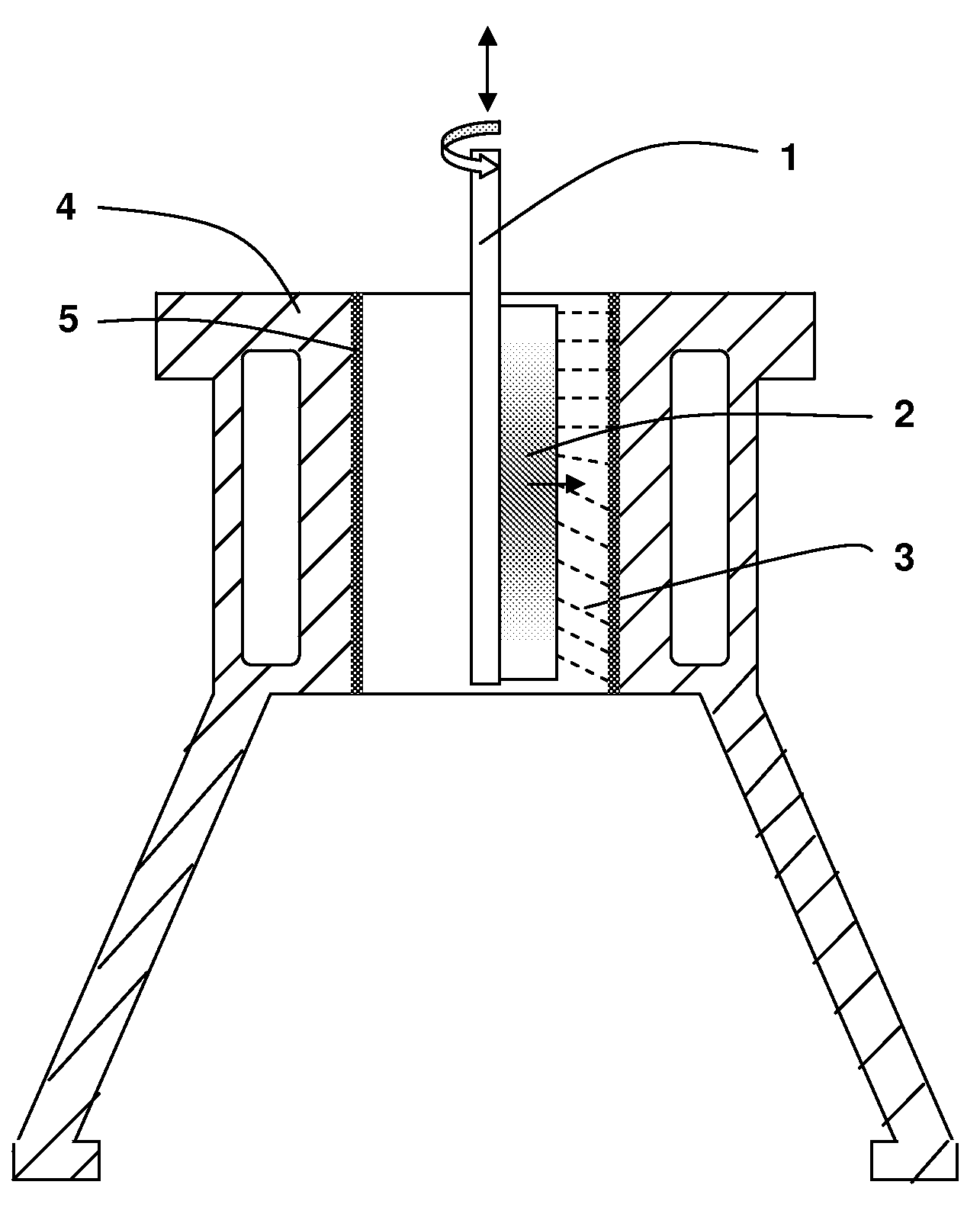
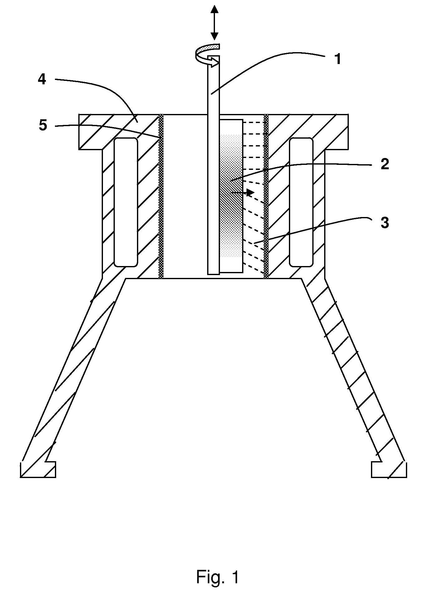
[0033]As shown in FIG. 1, a rotating hollow shaft 1 with one to four spraying heads 2, which is connected to a high voltage power supply, sprays an electrolytic solution 3 onto an interior surface of an Al—Si cylinder or engine block 4 bore 5. For multiple cylinders or bores, the above spraying head is required for each of cylinders or bores. For a V6 engine which has six cylinder bores, six above systems are usually needed.

[0034]When the process starts, the surface of said Al—Si alloy is electrochemically etched first by the alkaline solution. The etched Al matrix surface then grows with the formation of a thin oxide layer produced by plasma oxidation when the applied voltage increases, making the coated surface smoother than the etched surface. The dielectric plasma discharges on the oxide surface also cause a large number of dimples on its surface that can be favorably utilized as reservoirs of oil lubricants for reduction of friction and shear force during tribological applicati...

example 2

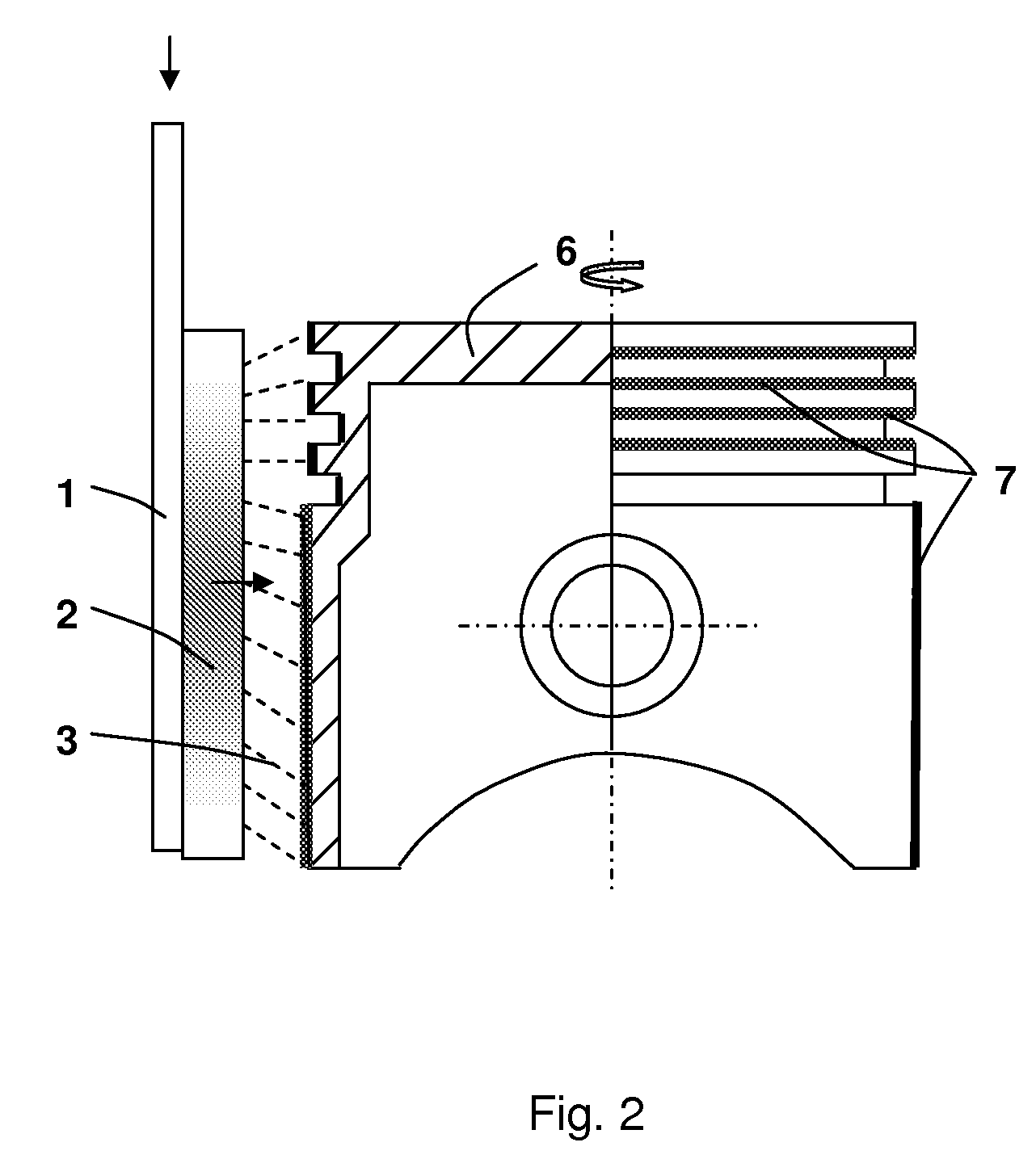
[0036]As shown in FIG. 2, a fixed hollow shaft 1 with one spraying head 2 sprays an electrolytic solution 3 onto the exterior surfaces of an Al—Si piston 6. The oxide coating forms on the exterior surfaces of the piston 7.

[0037]For instance, the as-prepared thin coating, of 0.5 to 5 microns in thickness, on the exterior surface of said a piston can reduce a mild and severe wear problem.

example 3

[0038]The oxide coating on an Al—Si alloy and Mg component eliminates metal-to-metal contact in a tribological system. The coating on engine block bores and pistons made of any of the said alloys can withstand a higher heat impact than its bare alloy bores and pistons. Therefore, the oxide coating would reduce the risk of adhesive or scuffing wear. The coated engine block bores also have a thermal conductivity similar to metallic engine bores, which would improve heat dissipation and reduce engine bore distortions. This kind of oxide coating is applied particularly onto engine bores and pistons made of Al and Mg alloys.


PUM

PropertyMeasurementUnit
voltageaaaaaaaaaa
thicknessaaaaaaaaaa
thicknessaaaaaaaaaa

Abstract

This invention involves a process of forming an oxide coating with dimples on Al, Mg and Ti alloys. The oxide coating with dimples on its surface is produced by the process consisting of an electrochemical etching on the surface of those alloys followed by plasma oxidation in an alkaline electrolytic solution using a high voltage power supply. The as-prepared coating has smooth surface finish and improved properties being suitable for wear and corrosion protection of materials which have contacts with each other. The present invention can also be applied onto Al—Si and Mg alloys for wear and corrosion-wear prevention of sleeveless aluminium and magnesium engines.

Description

TECHNICAL FIELD[0001]This invention relates to a process dealing with surface modification of aluminium, aluminium-silicon, magnesium, and titanium alloys for wear and corrosion prevention.BACKGROUND OF THE INVENTION[0002]Being lightweight will improve fuel efficiency and reduce emission of vehicles, so using Al, Mg, and Ti alloys as weight-saving materials has become increasingly important in the automotive and aerospace industries. Al and Mg sheets and extrusions have been found more and more applications in the transportation vehicles. Cast Al—Si alloys and Mg alloys have been or will be used in powertrain applications as lightweight components. There is a trend of development of Al and Mg sleeveless engines to further reduce vehicle weight. However, the sliding wear problem on the Al and Mg cylinder bores has to be dissolved before sleeveless Al and Mg engines are in use. There is another trend in usage of alternative fuels, for instances, biofuels such as E85, 85% ethanol and 1...

Claims


Application Information

Patent Timeline
Patent Type & Authority Applications(United States)
IPC IPC(8): C23C14/02
CPCC23C8/02
Inventor NIE, XUEYUANZHANG, JINGZENG
Owner NIE XUEYUAN
Learn More