Substrate processing method and substrate processing apparatus

Active Publication Date: 2008-07-31
TOKYO ELECTRON LTD
View PDF8 Cites 10 Cited by
  • Summary
  • Abstract
  • Description
  • Claims
  • Application Information

AI Technical Summary

Benefits of technology

[0015]According to the first aspect of the present invention, the oxygen radicals are supplied toward the substrate before the dry etching is carried out again after the gas supplying step. When the deposit is removed in the gas supplying step, the silicon base material becomes exposed on the side face of the trench. The oxygen radicals react with the exposed silicon base material to form an oxide film on the side face of the trench. The oxide film protects the side face of the trench from the plasma used in the dry etching that is carried out again. As a result, the trench can be prevented from becoming deformed.
[0017]According to the first aspect of the present invention, because the flow rate of the hydrogen fluoride gas supplied in the gas supplying step is 2000 sccm to 3000 sccm, a sufficient amount of hydrogen fluoride gas can be supplied toward the substrate, and hence the deposit can be reliably removed.
[0019]According to the first aspect of the present invention, the length of time that the hydrogen fluoride gas is supplied in the gas supplying step is not more than 30 seconds. The absolute amount of deposit produced in the dry etching of silicon is relatively small, and hence the deposit can be removed through etching using the hydrogen fluoride gas in a short time. Therefore, even if the length of time that the hydrogen fluoride gas is supplied is not more than 30 seconds, the deposit can be reliably removed.
[0021]According to the first aspect of the present invention, because the deposit to be removed in the gas supplying step is deposit that is produced through the dry etching and accumulates on the side face of the opening of the hard mask, the path over which the plasma passes through the opening of the hard mask and enters the trench can be secured, and hence the deep trench can be reliably formed in the silicon base material.

Problems solved by technology

When the substrate has reached a temperature of not less than 200° C., the hydrogen fluoride gas removes deposit produced through the dry etching of silicon, but does not remove the hard mask made of the silicon oxide film and / or the silicon nitride film.

Method used


Image

  • Substrate processing method and substrate processing apparatus
  • Substrate processing method and substrate processing apparatus
  • Substrate processing method and substrate processing apparatus

Examples


Embodiment Construction

[0028]The present invention will now be described in detail with reference to the drawings showing a preferred embodiment thereof.

[0029]First, a description will be given of a substrate processing apparatus according to an embodiment of the present invention.

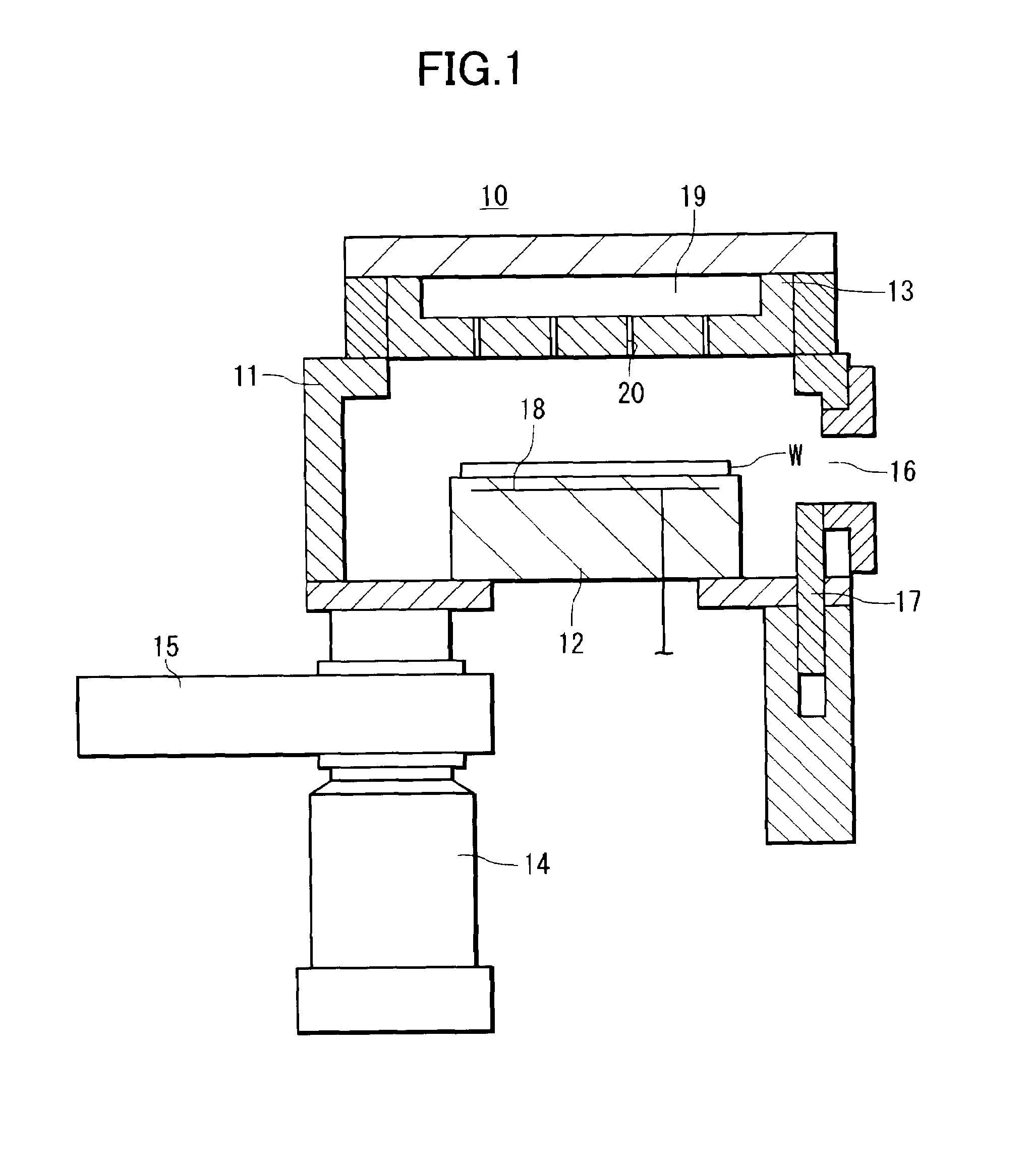
[0030]FIG. 1 is a sectional view schematically showing the construction of the substrate processing apparatus according to the present embodiment.

[0031]As shown in FIG. 1, the substrate processing apparatus 10 has a wafer housing chamber (hereinafter referred to merely as the “chamber”) 11 in which a wafer W (substrate) in FIG. 4A is housed, a mounting stage 12 that is disposed in the chamber 11 and on which the wafer W is mounted, a shower head 13 (gas supplying unit) that is disposed in an upper portion of the chamber 11 such as to face the mounting stage 12, a TMP (turbo-molecular pump) 14 that exhausts gas and the like out of the chamber 11, and an APC (adaptive pressure control) valve 15 that is disposed between the chamber...


PUM

PropertyMeasurementUnit
Temperatureaaaaaaaaaa
Timeaaaaaaaaaa
Flow rateaaaaaaaaaa

Abstract

A substrate processing method that can selectively remove deposit produced through dry etching of silicon. A substrate has a silicon base material and a hard mask that is made of a silicon nitride film and / or a silicon oxide film and formed on the silicon base material, the hard mask having an opening to which at least part of the silicon base material is exposed. A trench corresponding to the opening is formed in the silicon base material through dry etching using plasma produced from halogenated gas. After the dry etching, the substrate is heated to a temperature of not less than 200° C., and then hydrogen fluoride gas and helium gas are supplied toward the substrate.

Description

BACKGROUND OF THE INVENTION[0001]1. Field of the Invention[0002]The present invention relates to a substrate processing method and a substrate processing apparatus, and in particular to a method of processing a substrate having a hard mask comprised of a silicon oxide film and / or a silicon nitride film.[0003]2. Description of the Related Art[0004]In the case of forming a trench or a hole in a silicon (Si) base material 40 of a semiconductor wafer (hereinafter referred to merely as a “wafer”) W as a substrate that has the silicon base material 40 and a silicon nitride (SiN) film 41 formed on the silicon base material 40, the wafer W is subjected to dry etching using plasma 44 of halogenated gas such as hydrogen bromide (HBr).[0005]In the dry etching, a hard mask 42 that is a film made of BSG (boron silicate glass) formed on the silicon nitride film 41 is used. The hard mask 42 has an opening 43 to which the silicon base material 40 is partially exposed. The plasma 44 enters the openi...

Claims


Application Information

Patent Timeline
IPC IPC(8): H01L21/3065C23F1/08
CPCH01L21/3065H01L21/02057
Inventor NISHIMURA, EIICHIKATO, CHIESHIMIZU, AKITAKATAKAHASHI, HIROYUKI
Owner TOKYO ELECTRON LTD
Why Eureka
Try Eureka