
Method For Operating a Pulsed Arc Evaporation Source and Vacuum Process System Comprising Said Pulsed Arc Evaporation Source

Active Publication Date: 2008-07-24
OERLIKON SURFACE SOLUTIONS AG PFAFFIKON
View PDF4 Cites 18 Cited by
  • Summary
  • Abstract
  • Description
  • Claims
  • Application Information

AI Technical Summary

Benefits of technology

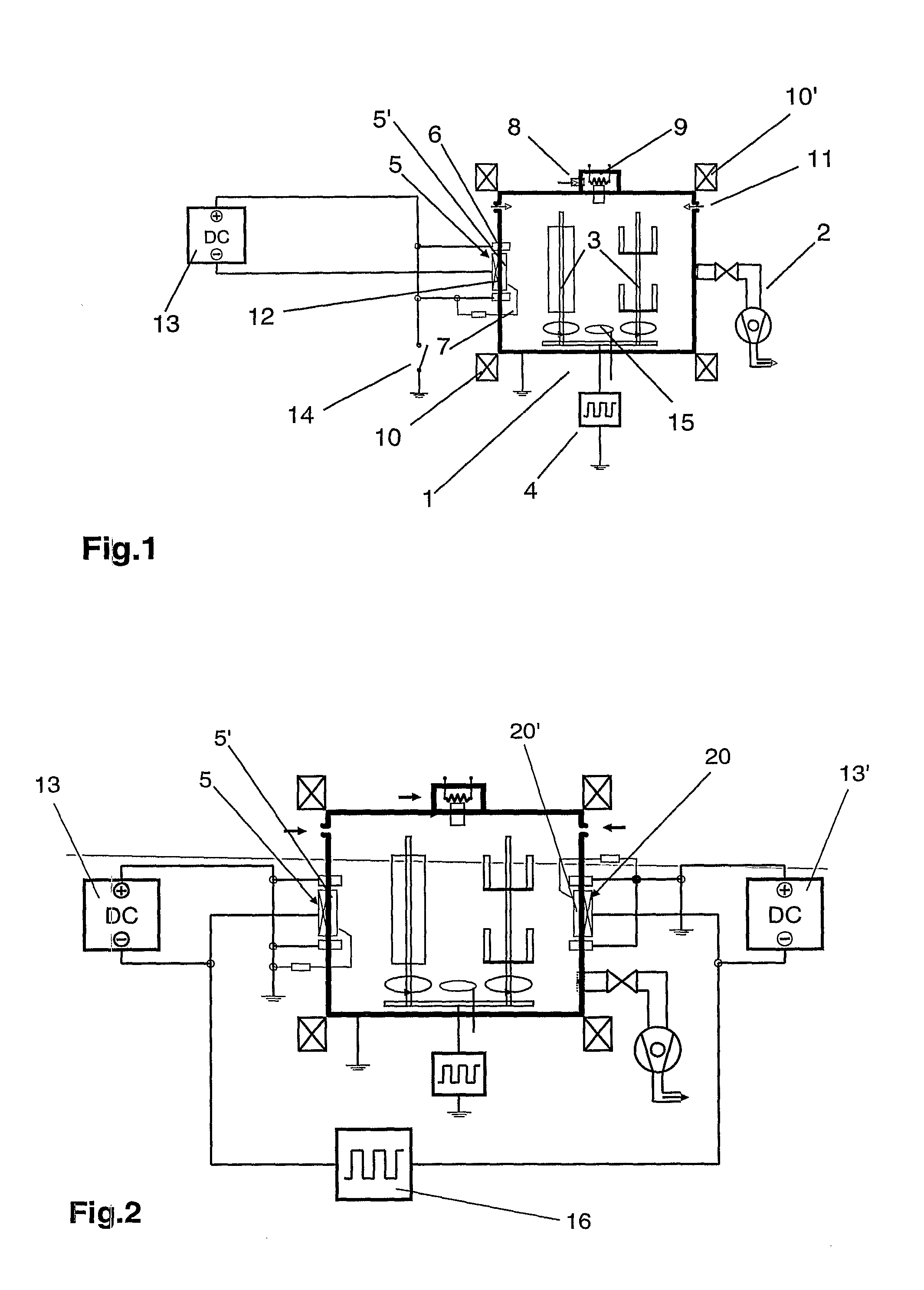
The present invention solves the problem of reducing the size and frequency of splatters in reactive processes for the production of insulating layers. It also improves process control, evaporation rates, layer quality, homogeneity of the reaction, and reduces surface roughness of the deposited layer. The invention provides a vacuum process installation with an arc evaporator source connected to a DC power supply and a second electrode, which can be a separate arc evaporator source or a workpiece holder. The two electrodes are connected with a pulsed power supply to create an additional discharge gap for better ionization of the involved materials. The invention allows for a high degree of ionization, good controllability of the process, and high efficiency of the process without requiring expensive pulsed power supplies. The configuration with two arc evaporators is particularly suitable for the deposition of layers from a metallic target using reactive gas. The invention also reduces splatter formation and improves the quality of non-conducting layers.

Problems solved by technology

A significant disadvantage with these sources comprises that in the proximity of the cathode spot very rapidly proceeding melting occurs on the target surface, whereby drops are formed, so-called droplets, which are hurled away as splatters and subsequently condense on the workpiece and consequently have an undesirable effect on the layer properties.
With high requirements made of the layer quality, layers generated thusly can often not be commercially applied.
While it has already been possible to partially raise the ionization with pulse operation, however, depending on the setting of the operating parameters, the formation of splatters was additionally even negatively affected.
The use of reactive gases for the deposition of compounds from a metallic target in a reactive plasma was until now only possible within narrow limits, since the problem of splatter formation in such processes is additionally exacerbated, in particular if non-conducting, thus dielectric, layers are to be generated, such as for example oxides using oxygen as the reactive gas.
The re-coating of the target surfaces of the arc evaporator and of the counterelectrodes, such as the anodes and also other parts of the vacuum process installation, with a non-conducting layer leads to entirely unstable conditions and even to the quenching of the arc.
In this case the latter would have to be repeatedly newly ignited or it would thereby become entirely impossible to conduct the process.
In the reactive coating by means of an arc evaporator source there is a lack of reactivity and process stability, especially in the production of insulating layers.
Working with high frequency, such as is the case during sputtering, has so far failed due to the lacking technique of being able to operate high-power supplies with high frequencies.
In the case of oxidized target surfaces, repeated ignition via mechanical contact and by means of DC supplies is not possible.
Other types of fast ignition processes are technically complex and limited with respect to their ignition frequency.
The actual problems in reactive arc evaporation are the coating with insulating layers on the target and on the anode or the coating chamber.
These coatings increase the burn voltage of the spark discharge, lead to increased splatters and sparkovers, an unstable process, which ends in an interruption of the spark discharge.
A highly diluted reactive gas (for example argon / oxygen mixture) can slow the accretion on the target, however, it cannot solve the fundamental problem of process instability.
While the proposal according to U.S. Pat. No. 5,103,766 to operate the cathode and the anode optionally with a new ignition each time, contributes to process stability, however, it does lead to increased splatters.
These conglomerates impinge as such onto the substrate and result in coarse layers, and it has not been possible fully to react-through the splatters.
Avoidance or fragmentation of these splatters was so far not successful, especially not for reactive coating processes.
With respect to prior art, a summary of the following disadvantages is provided:1. The reactivity in coating by means of cathode arc evaporation is unsatisfactory.2. There is no fundamental solution of the problematic of splatters: conglomerates (splatters) are not fully reacted-through—>roughness of the coating surface, constancy of the coating composition and stoichiometry.3. No stable processes are possible for the deposition of insulating layers.4. The subsequent ionization of splatters is unsatisfactory.5. Unsatisfactory possibilities of realizing low-temperature processes.6. Further reduction of the thermal loading of the substrates is unsatisfactory.

Method used


Image

  • Method For Operating a Pulsed Arc Evaporation Source and Vacuum Process System Comprising Said Pulsed Arc Evaporation Source
  • Method For Operating a Pulsed Arc Evaporation Source and Vacuum Process System Comprising Said Pulsed Arc Evaporation Source
  • Method For Operating a Pulsed Arc Evaporation Source and Vacuum Process System Comprising Said Pulsed Arc Evaporation Source

Examples


example 2

[0106]While in the above example the production of an Al—Cr—O layer was described, in which only two spark targets were utilized, in the following the process for a pure aluminum oxide layer utilizing 4 spark targets will be described:

[0107]For the coatings, hard metal indexable inserts (tungsten carbide) were used as substrates, which had already been coated in a preceding process with a 1.5 μm thick TiN layer. The substrates were subjected to a pretreatment, which was substantially identical to the above described steps 1 to 5. Before the coating with the functional layer, no special intermediate layer was deposited, i.e. the functional layer was directly deposited on the TiN base and steps 6 and 7 were omitted. For the deposition of the functional layer (8) work took place with four spark targets and the following process parameters were used:[0108]4 Al targets operated at 170 A DC each[0109]bipolar current pulses, corresponding to FIG. 2, of 2 Al targets each with an output volt...

example 3

[0120]The next example relates to the production of a zirconium oxide layer. Before the coating with the functional layer proper, the substrates were coated with an intermediate layer of ZrN. For this coating 4 targets were used for the work, which was operated at a partial pressure of nitrogen of 2 Pa with 170 A each.

[0121]The substrate temperature was 500° C. and a substrate bias of −150 V was used. The coating time for this intermediate layer was 6 min.

[0122]For the deposition of the functional layer (8) work also took place with four spark targets, corresponding to FIG. 2, and the following process parameters were used:[0123]4 Zr targets operated at 170 A DC each[0124]bipolar current pulses of 2 Zr targets each with an output voltage of 100 V at the power supply and positive and negative pulse widths of 20 μs each[0125]Argon flow: 50 sccm[0126]Oxygen flow: 700 sccm[0127]Substrate bias: DC bipolarly pulsed, + / −40 V, 38 μs negative, 4 μs positive[0128]Substrate temperature: 500° C...

example 4

[0136]In the last example the production and analysis of an SiAlN layer will be discussed.

[0137]Before the coating proper with the functional layer, the substrates were coated with an intermediate layer of TiN. For this coating the work took place with 2 targets, corresponding to FIG. 2, which were operated at 180 A each at a partial pressure of nitrogen of 0.8 Pa. The substrate temperature was 500° C. and a substrate bias of −150 V was used. The coating time for this intermediate layer was 5 min.[0138]2 SiAl targets with a ratio of Si / Al of 70 / 30 were operated at 170 A DC each[0139]bipolar current pulses of the 2 SiAl targets with an output voltage of 100 V at the power supply and positive and negative pulse widths of 20 μs each[0140]Argon flow: 50 sccm[0141]Oxygen flow: 800 sccm[0142]Substrate bias: DC bipolarly pulsed, + / −40 V, 38 μs negative, 4 μs positive[0143]Substrate temperature: 410° C.

[0144]The layer obtained in this manner was characterized through the following measureme...


PUM


Abstract

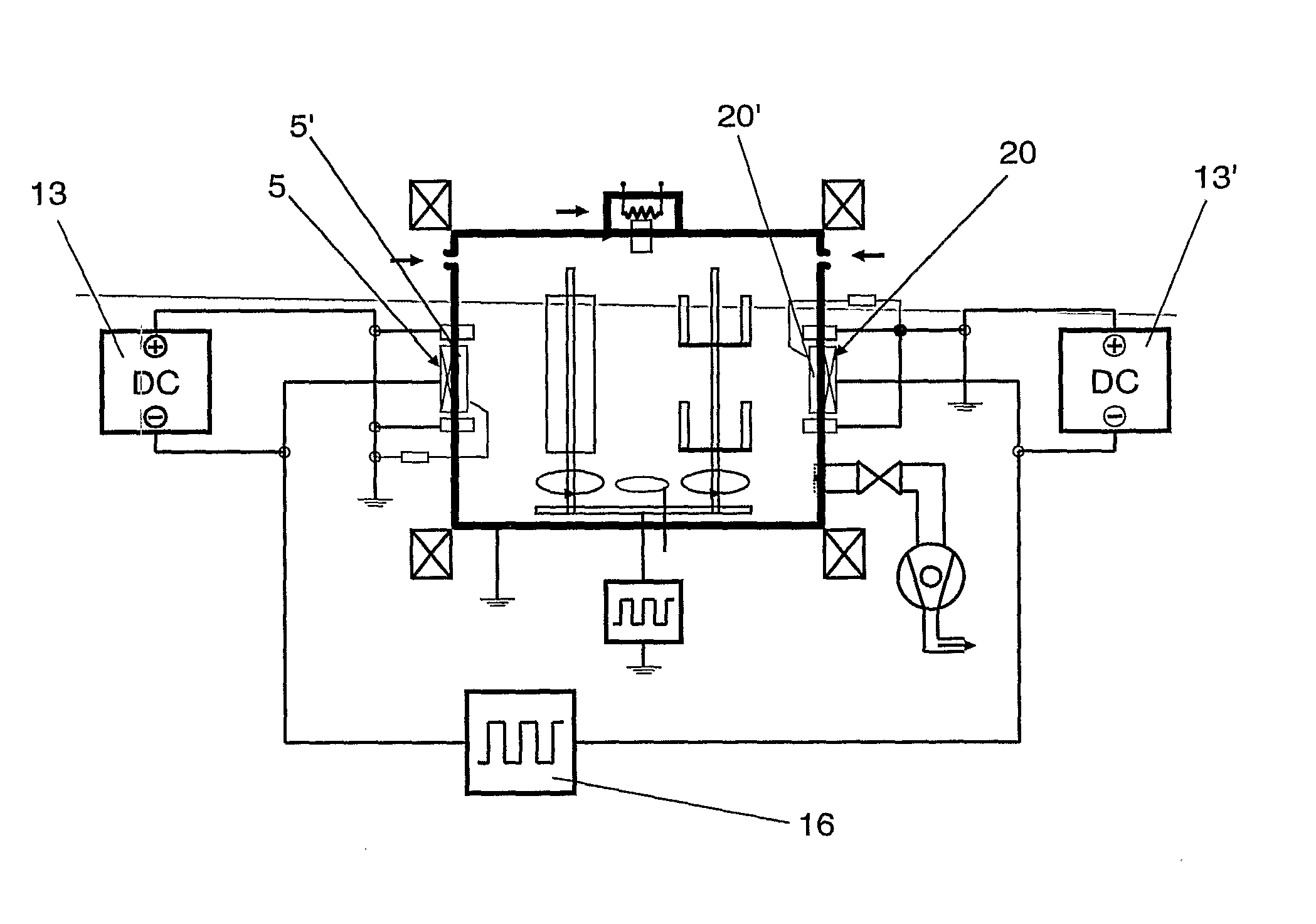
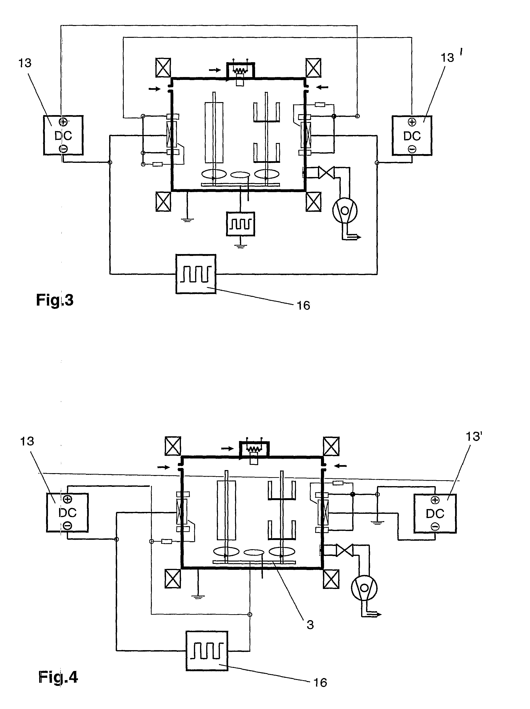
A vacuum process system for surface-treating work pieces uses an arc evaporation source. The system has a first electrode connected to a DC power source and a second electrode, disposed separately from the arc evaporation source. The two electrodes are operated while being connected to a single pulsed power supply.

Description

FIELD AND BACKGROUND OF THE INVENTION[0001]The invention relates to a vacuum process installation for the surface treatment of workpieces with an arc evaporator source according to the preamble of claim 1 as well as to a method for operating an arc evaporator source according to the preamble of claim 14.[0002]The operation of arc evaporator sources, also known as spark cathodes, by feeding with electrical pulses has already been known in prior art for a relatively long time. With arc evaporator sources high evaporation rates and consequently high deposition rates can be economically attained in coating. The structuring of such a source can, moreover, be technically relatively easily realized as long as higher requirements are not made of the pulse operation and the pulsing is more or less restricted to the ignition of a DC discharge. These sources operate at currents typically in the range of approximately 100 A and more, and at voltages of a few volts to a few tens of volts, which ...

Claims


Application Information

Patent Timeline
Patent Type & Authority Applications(United States)
IPC IPC(8): C23C14/35C23C14/00
CPCC23C14/024C23C14/0641C23C14/08C23C14/081C23C14/083F05D2230/313F01D5/288H01J37/32055H01J37/34H01J37/3444C23C14/325C23C14/00C23C14/28C23C14/32H01J37/32
Inventor RAMM, JURGENWIDRIG, BENOLENDI, DANIELDERFLINGER, VOLKERREITER, ANDREAS
Owner OERLIKON SURFACE SOLUTIONS AG PFAFFIKON
Learn More