Co-molded direct flock and flock transfer and methods of making same

a technology of direct flocking and co-molded articles, which is applied in the field of molded articles with flocked surfaces, can solve the problems of increasing the cost and time of processing, requiring additional processing and cost, and a large number of problems with imd technology, and achieves the effects of low cost, low cost and modest capital investmen

Inactive Publication Date: 2008-06-26
HIGH VOLTAGE GRAPHICS
View PDF101 Cites 23 Cited by
  • Summary
  • Abstract
  • Description
  • Claims
  • Application Information

AI Technical Summary

Benefits of technology

[0014]The mold insert may be pre-formed into a three dimensional shape, such as by thermoforming, vacuum forming and hydro-forming techniques. The three dimensional shape helps the mold insert maintain a desired position in the mold during resin injection. To provide melt bonding with the resin, the backing film preferably has a melting point that is at or above the maximum temperature experienced by the backing film during molding and a chemical composition compatible with that of the resin. As in the case of the adhesive layer, the backing film is preferably a cast or extruded continuous film and not a fabric. Another adhesive may be located between the permanent adhesive layer and the backing film to adhere the adhesive layer to the backing film.
[0015]The present invention can have a number of advantages compared to conventionally decorated molded articles. First, attractive, multicolored flock insert molded articles can be manufactured inexpensively and in high volumes. Second, the process can be relatively simple and require at most a modest capital investment. Third, imaging techniques such as screen printing or cutting permits portions of the design to be easily omitted or separated, as desired. The ability to create voids in the finished design where desired, could eliminate subsequent cutting and / or picking out of material to be eliminated (like the center of the letter “O”). This ability permits novel design configurations, such as designs where the backing film is exposed as part of the overall design. Alternatively, part of the adhesive can be left exposed and the adhesive then sprinkled with or dipped into a design medium to fill the exposed area of the resin dispersion. The exposed area can thus be used for inclusion of different types of design media materials (like textiles, holograms, glitter particles, beads, etc.) incorporated into the molded article to create interesting, mixed media looks. Fourth, the various processes described herein can produce multi-colored flocked surfaces on molded articles. Such articles have higher perceived values (as one can make attractive multi-colored designs, simulated textile looks, logos, etc.) when compared to single colored molded articles. The (pre-colored or permanently colored) multi-colored flock (either producer colored (or pigment-in-colored) or dyed flock) can be selected to provide superior soil and stain concealment and resistance to chemical or high UV exposure, which can be particularly important in automotive or outdoor use. In contrast, single colored molded articles will readily show lint, soil, stains, etc. Additionally, multi-colored flock can have functional value, such as graphically or visually producing strips for a grip handle, insulation value, and other benefits, such as sweat absorption and comfort.

Problems solved by technology

These methods are most often post-molding operations requiring additional processing and cost and time.
In addition, the resulting quality of the product is often low, due to the low quality of adhesion or unevenness of the coating.
However, a number of problems have developed with the IMD technology.
By way of example, the ink or decoration is typically unable to remain stable during the heat and force of injecting the resins into the mold.
During resin injection into the mold, the decoration is often dislocated, leading to an unacceptable finished article.
The pressure, heat, and shear force exerted on the decoration during resin injection may also cause the decoration surface to become smeared, crushed, or otherwise disturbed during injection molding.

Method used


Image

  • Co-molded direct flock and flock transfer and methods of making same
  • Co-molded direct flock and flock transfer and methods of making same
  • Co-molded direct flock and flock transfer and methods of making same

Examples


Embodiment Construction

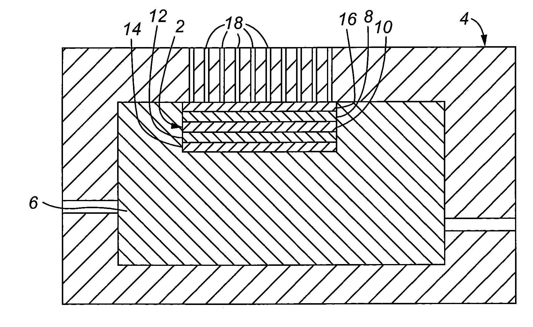
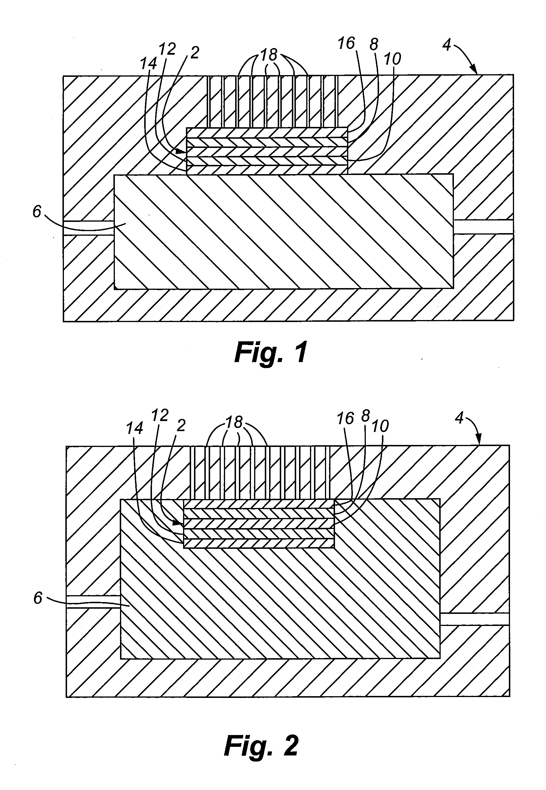
[0034]In one embodiment, a flock heat transfer type media is used rather than ink-printed film inserts or decorations to provide a plush, evenly-coated, three-dimensional single or multi-colored textured decoration molded together with the hot resins when the part is formed. Using flock transfer media, a plushly textured decoration is permanently attached to the surface of the molded part. To accomplish this the hot melt adhesive commonly used with flock heat transfer manufacturing is eliminated so it will not liquefy and ooze out around the decoration in the mold. In addition, another adhesive, such as a tie coat material or other compatible film, may be used instead of a normal hot melt to prevent oozing and to promote adhesion, melt bond and / or chemical compatibility with the molding resin, when injecting molding a flock transfer directly to the polymer molded article.

[0035]The mold may have a depression or locating pins or other mechanical parts to assist with aligning and holdi...


PUM

PropertyMeasurementUnit
temperatureaaaaaaaaaa
resistant pressureaaaaaaaaaa

Abstract

A method of decorating a molded article is provided that includes the steps of:
(a) providing a mold insert comprising a plurality of flock fibers and a permanent adhesive layer;
(b) positioning the mold insert in a mold; and
(c) introducing resin into the mold, such that a resin contacts the mold insert to form a molded article. The melting point of the permanent adhesive layer is preferably greater than a temperature of the resin during molding.

Description

CROSS-REFERENCE TO RELATED APPLICATIONS[0001]The present application is a divisional application of U.S. application Ser. No. 10 / 394,357, filed Mar. 21, 2003, which is a continuation-in-part of each of U.S. patent application Ser. No. 09 / 629,746, filed Jul. 31, 2000, and Ser. No. 09 / 621,830, filed Jul. 24, 2000, and claims the benefits under 35 U.S.C.§119 of each of U.S. Provisional Application Ser. Nos. 60 / 366,580, filed Mar. 21, 2002; 60 / 393,362, filed Jul. 3, 2002; 60 / 416,098, filed Oct. 4, 2002; and 60 / 443,986 filed Jan. 30, 2003, each of which is to Abrams and is incorporated herein by this reference.FIELD OF THE INVENTION[0002]This invention relates generally to flocked articles and specifically to molded articles having flocked surfaces.BACKGROUND OF THE INVENTION[0003]It is often desirable to decorate molded plastic parts for aesthetic or practical purposes. Injection molded articles are often decorated using inks, screen printing, pad printing, direct electrostatic flocking...

Claims


Application Information

Patent Timeline
Patent Type & Authority Applications(United States)
IPC IPC(8): B29C70/68B29C65/52B05D5/00B05D5/08
CPCB05D1/16B05D7/02B29K2715/006B29K2713/00B29C45/14811
Inventor ABRAMS, LOUIS BROWN
Owner HIGH VOLTAGE GRAPHICS
Why Eureka
Try Eureka