
Electrical storage device heater for vehicle

a technology for electric storage devices and heaters, which is applied in the direction of engine starters, battery/fuel cell control arrangements, machines/engines, etc., can solve the problems of reducing vehicle performance, fuel economy and drivability, and unable to effectively operate in extremely cold climates, and achieves the effect of easy omission

Active Publication Date: 2011-11-10
FORD GLOBAL TECH LLC
View PDF5 Cites 11 Cited by
  • Summary
  • Abstract
  • Description
  • Claims
  • Application Information

AI Technical Summary

Benefits of technology

Ensures reliable vehicle starting and optimal performance across various climates by maintaining battery temperature, outperforming self-powered heaters in duration and temperature range.

Problems solved by technology

Currently available electric and hybrid electric vehicles tend to operate more effectively in moderate and warm climates and less effectively in extremely cold climates.
This is because high voltage traction batteries tend to lose power as battery cell temperature drops (e.g., below approx.
This power decrease results in reduced vehicle performance, fuel economy and drivability.
At extremely low temperatures, the traction battery may have insufficient power to even start the vehicle.
Sustaining the battery temperature at a desired level can be challenging because the battery temperature can be affected by many factors, such as the battery condition, the battery cell temperature, the battery charge condition when the vehicle is turned off, and the ambient temperature.
Self-powered battery heaters are able to maintain a minimum battery temperature level only for short time periods because the amount of power available for heating is limited by the storage capacity of the battery itself.
Thus, self-powered battery heaters are unsuitable when the battery needs to be heated for an extended time period and / or when the battery needs to be warmed to a higher temperature to ensure optimal vehicle performance.

Method used


Image

  • Electrical storage device heater for vehicle
  • Electrical storage device heater for vehicle
  • Electrical storage device heater for vehicle

Examples


Embodiment Construction

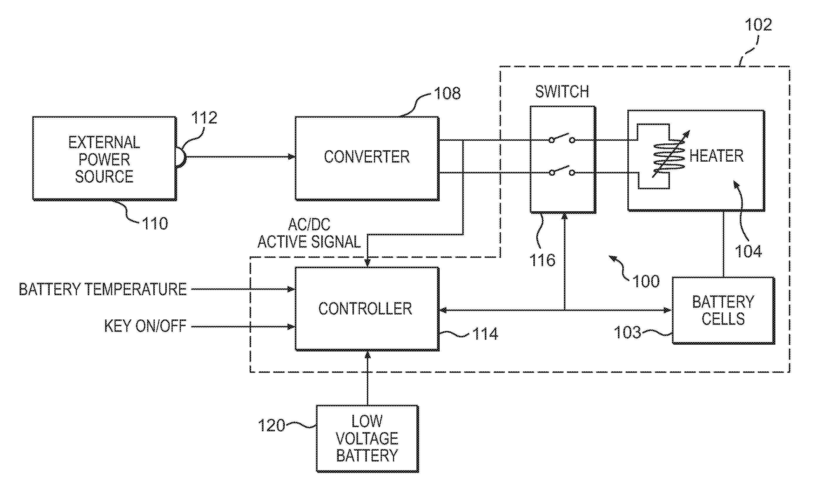
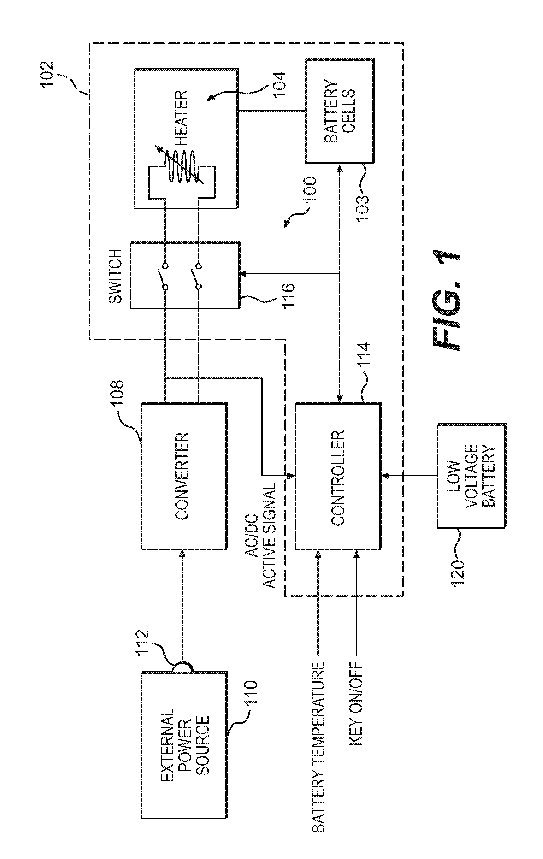
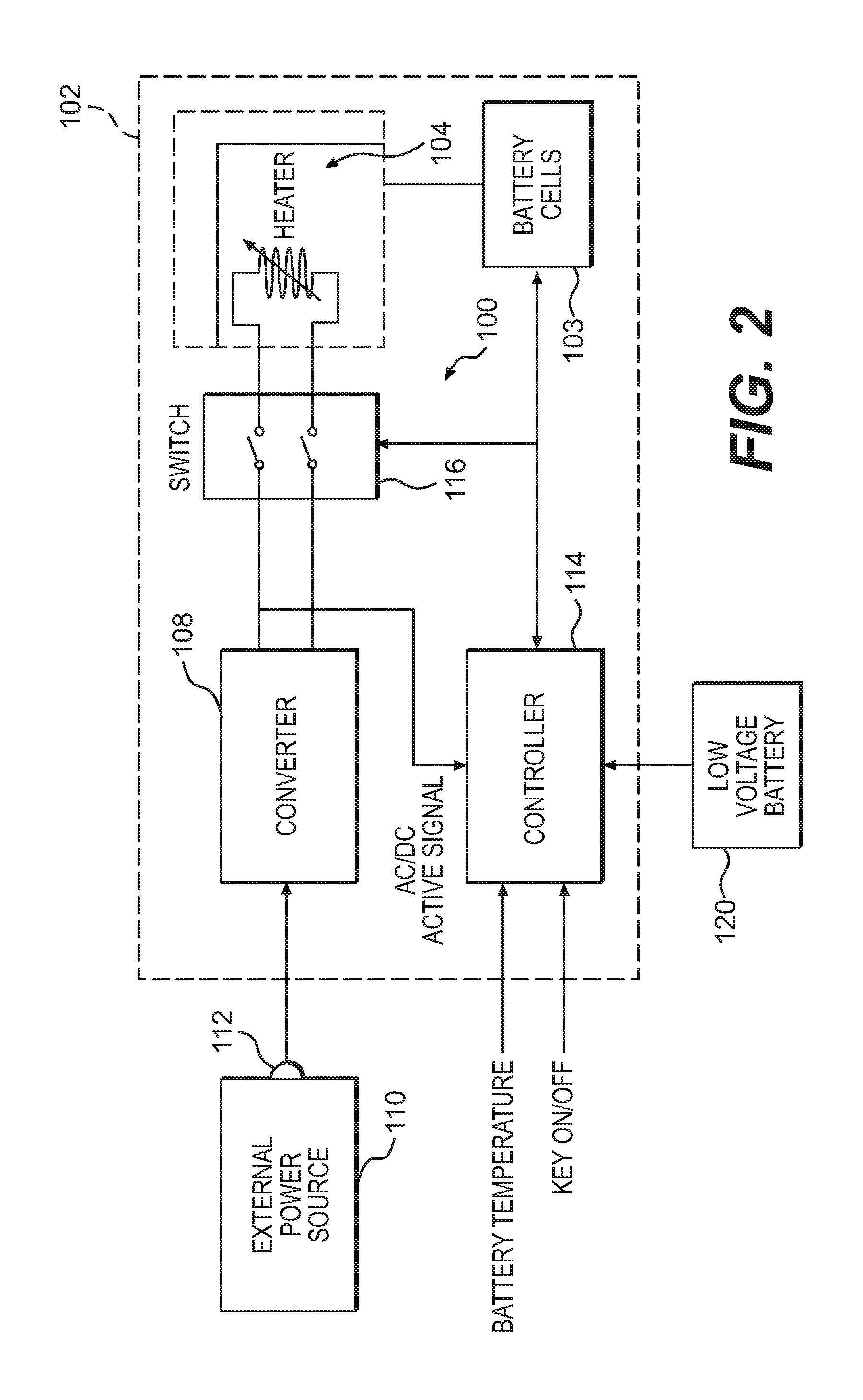
[0014]FIG. 1 is a block diagram illustrating components of a battery heater system 100 according to one embodiment of the invention. Generally, the invention is directed to a vehicle battery heater system 100 that is powered by an external power source e.g., a 120V AC power source outside the vehicle or a supplemental low-voltage or accessory battery on-board the vehicle) outside a high-voltage battery system 102 or other electrical storage device. The battery system 102 includes one or more battery cells 103. By using an external power source that is separate from the high-voltage battery system 102 to operate the heater system 100, the invention can keep the battery system 102 warm and regulate the temperature of the battery system 102 reliably when the vehicle is exposed to a cold environment.

[0015]As shown in FIG. 1, the battery heater system 100 includes a heater 104 for warming the battery cells 103. The heater 104 itself may have any configuration known and appreciated in the...


PUM


Abstract

A heater system for an electrical storage device, such as a high voltage traction battery, is connectable to an external AC power source maintain a proper temperature of the battery as long as the system remains connected to the external power source. The battery temperature can be maintained at a level that ensures that the vehicle will start even in extremely cold climates. The heater system includes a heater disposed within the battery itself. Other system components, such as an AC / DC converter and a control module, may be connected to the battery heater system outside of the battery, allowing the battery heater system to act as a modular component that can be easily included in or excluded from a vehicle as an option, either alone or in a package with an engine block heater. The battery heater system is designed so that it can be connected along with the engine block heater to the AC power source using a single common connector.

Description

CROSS REFERENCE TO RELATED APPLICATIONS[0001]This application is a continuation of U.S. patent application Ser. No. 10 / 897,695, which was filed on Jul. 23, 2004.TECHNICAL FIELD OF THE INVENTION[0002]The present invention relates generally to thermal controls for an electrical storage device in a vehicle. More particularly, the present invention relates to a system and method for heating the electrical storage device.[0003]Electric and hybrid electric vehicles have become increasingly popular to meet the demand for fuel-efficient, environmentally-friendly transportation. Such vehicles often include an electrical storage device, such as a high-voltage traction battery, for powering an electric motor to drive the vehicle, either alone or in conjunction with an internal combustion engine, fuel cell engine, or other prime mover.[0004]Currently available electric and hybrid electric vehicles tend to operate more effectively in moderate and warm climates and less effectively in extremely c...

Claims


Application Information

Patent Timeline
Patent Type & Authority Applications(United States)
IPC IPC(8): H05B1/00B60K6/28F02N19/02
CPCB60K6/28H01M10/502B60L11/187B60L11/1875B60L2210/30B60W2510/246F02N11/0862F02N11/0866F02N11/14F02N19/02F02N2200/064Y02T10/7005Y02T10/705Y02T10/7241H01M10/5006B60K2001/008H01M10/63H01M10/615B60L58/24B60L58/27Y02T10/70Y02T10/72Y02E60/10B60W2510/244B60L1/02
Inventor ZHU, DOUGLASMATHEWS, JACOBMAGUIRE, PAXPADGETT, PATRICK
Owner FORD GLOBAL TECH LLC
Learn More