Manufacture of semiconductor device
a manufacturing method and semiconductor technology, applied in the direction of semiconductor devices, basic electric elements, electrical appliances, etc., can solve the problems of deterioration of the performance the high integration of the semiconductor device (semiconductor integrated circuit device), and the downsizing of the semiconductor device, so as to achieve the effect of activation
- Summary
- Abstract
- Description
- Claims
- Application Information
AI Technical Summary
Benefits of technology
Problems solved by technology
Method used
Image
Examples
first embodiment
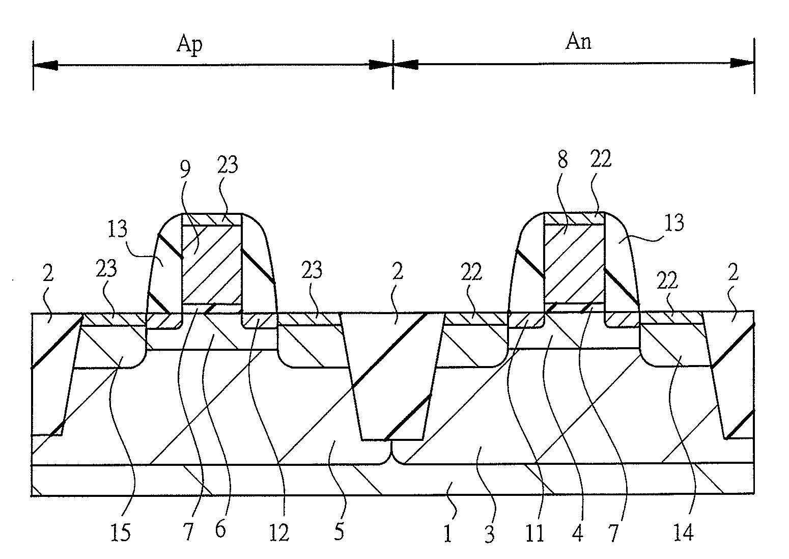
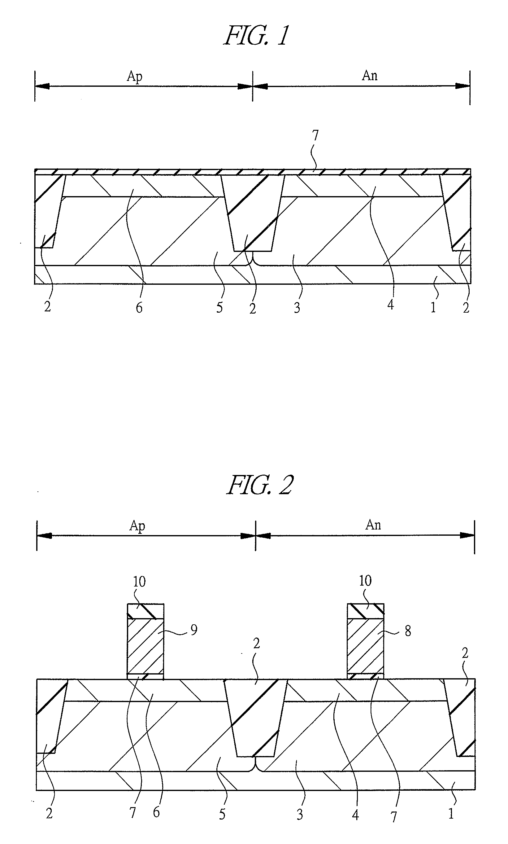
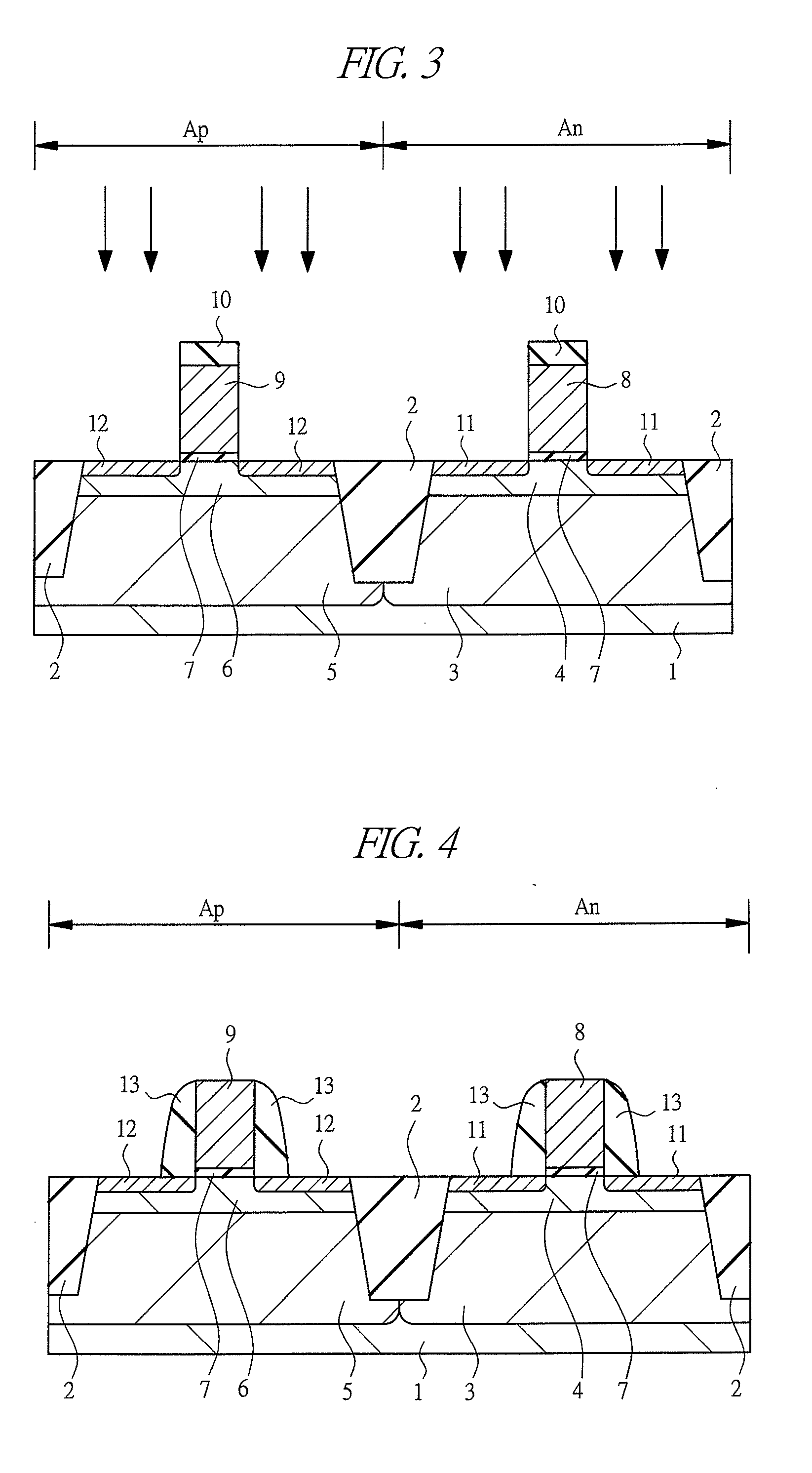
[0056]Manufacturing process of a semiconductor device according to the first embodiment will be described with reference to the drawings. FIG. 1 to FIG. 8 are cross-sectional views showing a principal part of a semiconductor device according to an embodiment of the present invention, for example, the manufacturing process of CMIS.
[0057]First, as shown in FIG. 1, for instance, a semiconductor substrate 1 made of p-type single-crystal silicon and having a resistivity in a range from about1 to 10 Ωcm is prepared. This semiconductor substrate 1 has a region Ap on which a p-channel MISFET (hereinafter, referred to as pMIS) is formed and a region An on which an n-channel MISFET (hereinafter, referred to as nMIS) is formed. In other words, a pMIS and an nMIS which constitute a CMIS are formed on the main surface of this semiconductor substrate 1.
[0058]Then, an element isolation region 2 is formed in the main surface of the semiconductor substrate 1. The element isolation region 2 is made o...
second embodiment
[0106]In the first embodiment, the case where a silicon dioxide layer is applied to the gate insulator 7 has been described. However, in the second embodiment, the case where a high-k layer is applied to the gate insulator 7 will be described. Since the manufacturing process up to the step of forming the gate insulator 7 is the same as that of the first embodiment, the description thereof will be omitted and the manufacturing process thereafter will be described.
[0107]As shown in FIG. 1, a stacked gate insulator HfSiO2 / HfO2 (high-k layer) with the thickness of about 0.5 nm / 3 nm is formed as the gate insulator 7 on the surface of the p-type well 3 and the n-type well 5 by a sputtering method or a CVD method. A composition ratio of HfSiO2 layer is, for example, Si / (Si+Hf)=10 to 50 atom %.
[0108]Next, as shown in FIG. 2, a metal layer made of Al, W, Ti or nitrides of these metals to be the gate electrodes 8 and 9 is formed by a sputtering method or a CVD method. For example, its thickne...
third embodiment
[0117]In the first embodiment, the case where the annealing treatment according to the present invention is applied to the process of activating impurities has been described. However, in the third embodiment, the case where it is applied to the siliciding step will be described.
[0118]FIG. 17 and FIG. 18 are sectional views showing the principal part in the manufacturing process of a semiconductor device according to the third embodiment. Since the manufacturing process up to the step shown in FIG. 7 is the same as that of the first embodiment, the description thereof will be omitted and the manufacturing process thereafter will be described.
[0119]As shown in FIG. 17, a nickel (Ni) layer 21 is formed to about 30 nm to 40 nm on the semiconductor substrate 1 having an nMIS formation region An and a pMIS formation region Ap by a conventional sputtering method or the like. In the third embodiment, this nickel layer 21 functions as a reflectance-controlling layer.
[0120]Then, the nickel l...
PUM
 Abstract
Description
Claims
Application Information
 - R&D
- Intellectual Property
- Life Sciences
- Materials
- Tech Scout
- Unparalleled Data Quality
- Higher Quality Content
- 60% Fewer Hallucinations
Browse by: Latest US Patents, China's latest patents, Technical Efficacy Thesaurus, Application Domain, Technology Topic, Popular Technical Reports.
© 2025 PatSnap. All rights reserved.Legal|Privacy policy|Modern Slavery Act Transparency Statement|Sitemap|About US| Contact US: help@patsnap.com


