
Electrolytic system and method for enhanced release and deposition of sub-surface and surface components

a technology of electrolysis and surface components, applied in the direction of hydrocarbon oil cracking process, separation process, borehole/well accessories, etc., can solve the problems of significant surfactant cost in relation to the benefits gained, high technological pathway, and large amount of oil remaining unrecovered, so as to maximize the extraction efficiency of the target component, improve the efficiency of the extraction process, and reduce the structure of operating costs

Active Publication Date: 2008-05-22
STRATEGIC RESOURCE OPTIMIZATION
View PDF9 Cites 47 Cited by
  • Summary
  • Abstract
  • Description
  • Claims
  • Application Information

AI Technical Summary

Benefits of technology

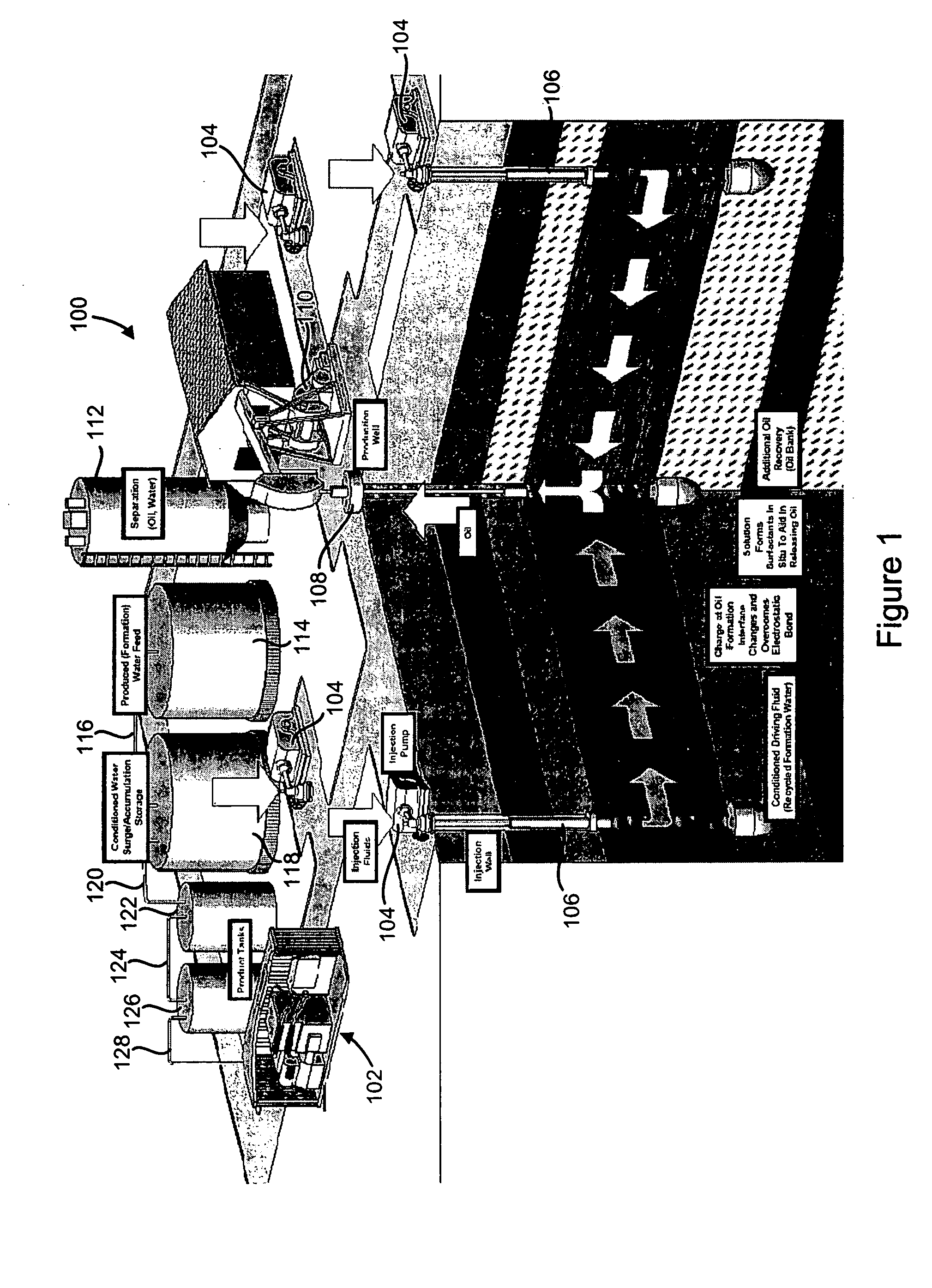
[0012]The above-described problems are solved and a technical advance achieved in the field by the present Electrolytic System and Method For Enhanced Release and Deposition of Sub-Surface and Surface Components (termed “electrolytic component removal system” herein), which functions to directly, variably, and reversibly change the electrochemical state of a carrier fluid to substantially aid and increase the recovery, deposition, concentration or sequestration of a wide range of subsurface components, such as fluids and minerals, or for use in surface processing. This is accomplished by directly altering the electrochemical state of subsurface components and changing the Zeta potential at the solid-liquid interface, solid-mineral interface, liquid-liquid interface, or strata. The carrier fluid is ionized prior to utilization by the addition or removal of electrons from the system (depending on application). The electrolytic component removal system uses an ionized carrier fluid to release / recover minerals and other components from the subsurface, and can also be utilized for above ground processing for beneficial, economic, and environmental utility.
[0013]This present invention, the electrolytic component removal system, directly acts on the electrochemical charge balance between the solid-liquid / solid-mineral interface to reversibly alter the electrochemical potential and overcome the technical impediments to efficiently increase fluid and mineral resource recoveries. The present electrolytic component removal system directly modifies the electrochemical properties of introduced or connate water to recover fluid or solid minerals and increase the extraction efficiency by controlling the electrochemical charge that trapped the deposit over geologic time. The electrolytic component removal system adjusts the electrochemical state of the carrier fluid to address variations in bonding potential that release the fluid and mineral components for improved recovery.
[0015]The present electrolytic component removal system controls the electrochemical state of subterranean geologic strata by ionizing a carrier fluid prior to its injection into the formation of interest. The ionized carrier fluid can use either a negative or reducing potential (excess of electrons) or a positive or oxidizing potential (lack of electrons), and the amount of charge can be adjusted to control a recovery or other operation. A fluid ionizer generates both solutions from the split stream exiting the ionizer subsystem. The electrical potential of the solutions can be controlled by adjusting current density, total dissolved solids, plate size and type, membrane type, voltage, fluid residence time, or a combination of these variables. This allows “tailoring” the injection fluid potential to maximize the extraction efficiency of the target component within a lower operating cost structure.
[0016]The present electrolytic component removal system also adjusts and controls the pH of the carrier fluid to improve efficiency of the extraction process. With an increase of the reducing potential used, typically the greater the pH of the carrier fluid. Conversely, the lower the reducing potential (increased oxidizing potential) used, typically the lower the pH of the carrier fluid.
[0017]Further, the present electrolytic component removal system controls the electrochemical state of subterranean strata without the introduction of expensive, complex or externally sourced substances, and reduces overall recovery costs. This allows the fluid or solid mineral components of beneficial and economic value to be extracted and processed at a lower cost than conventional methods, significantly advancing the state-of-the-art.

Problems solved by technology

It is a problem in the field of fluid and solid mineral extraction to efficiently extract subsurface components in subsurface deposits, reservoirs, or fields.
Thus, the majority of oil remains un-recovered though discovered, identified and with direct physical access by existing wells.
This technological pathway is expensive due to the costs of producing, processing, transporting, compressing, injecting, and recycling of valuable substances to recover additional hydrocarbons.
One limitation is the significant cost of surfactants in relation to the benefits gained.
Technical limitations of this approach include surfactant adsorption on the rock / solid interface and the effect of calcium / magnesium (e.g., hard water) interactions in the subsurface.
As with other chemical additive methods, the cost of the polymers is a significant disadvantage.
Additional limitations exist from adsorption of the polymer by the substrate and ineffectiveness in reducing oil saturation.
The quantity of chemicals needed for this application is significant and the costs of implementation reflect this requirement.
Technical limitations of this approach (beyond the logistics of substantial chemical handling include consumption of the alkaline materials by the geologic media, requiring additional chemicals to maintain the expected benefit.
This results in an increase in the water wettability and the displacement of oil from the pore.
As with other techniques, a limitation of this approach is the significant cost of producing and transporting the sulfonates in relation to the benefits gained.
One of the technical limitations is the stability of the micelle during flood displacement.
This approach is both capital intensive and has a significant operational cost burden for the duration of the operation.
Technical limiting factors are the large capacity of the RO systems required and the limitation of the dilution effect within the formation.
While the above examples are related to oil recovery, other fluid and solid mineral resource recoveries are faced with similar issues.
Mineral recovery efficiency is hampered by both technical and economic hurdles.
This has impeded the overall development of the resource endowment and improvements in extraction efficiency.
These applications have increased recovery efficiencies, but are approaching both technical and economic limits.
The introduction of external materials added for extraction may have unwanted (physical, geochemical, petrophysical or other) side effects that limit extraction efficiency and / or create environmental damage.

Method used


Image

  • Electrolytic system and method for enhanced release and deposition of sub-surface and surface components
  • Electrolytic system and method for enhanced release and deposition of sub-surface and surface components
  • Electrolytic system and method for enhanced release and deposition of sub-surface and surface components

Examples


example 1

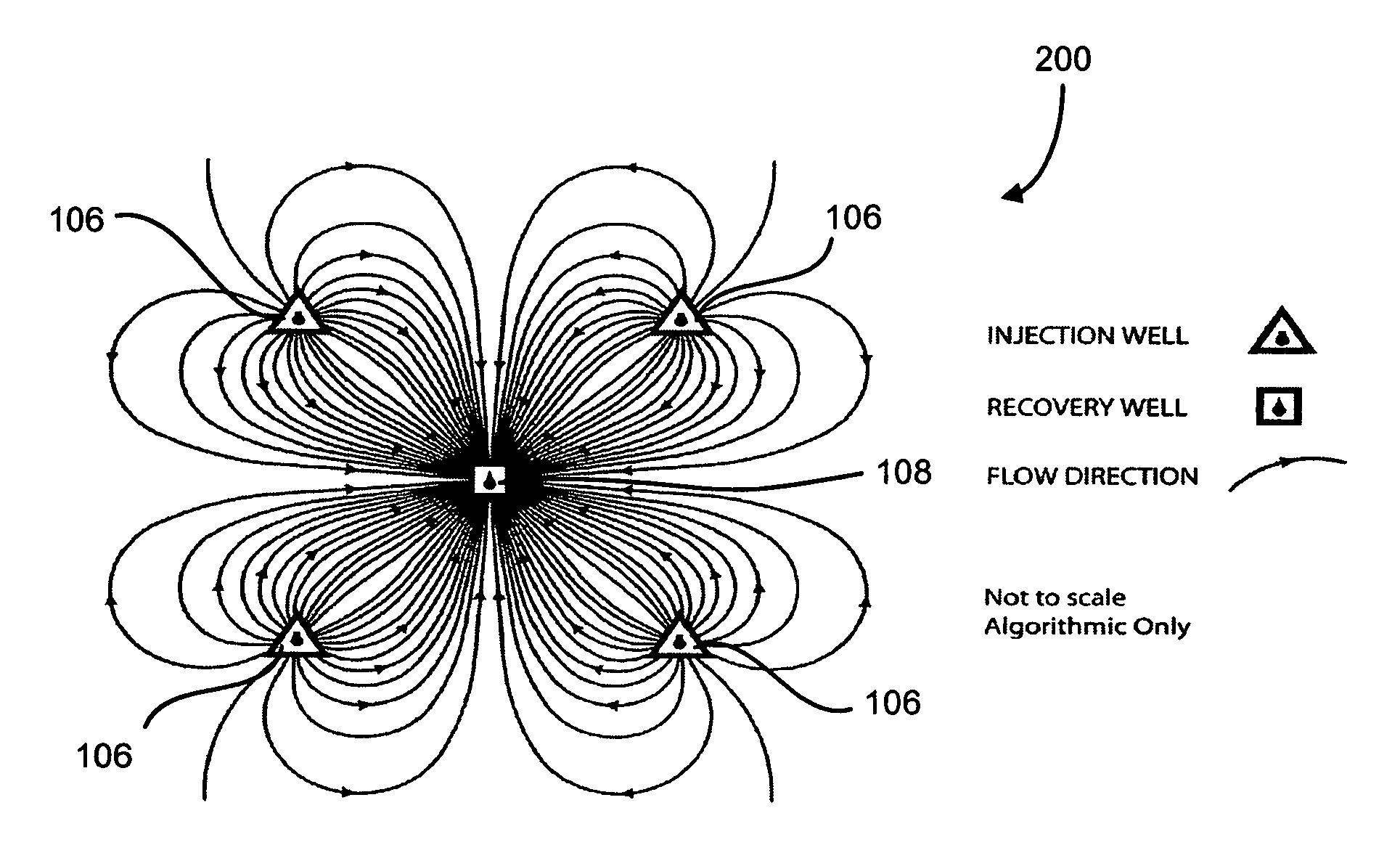
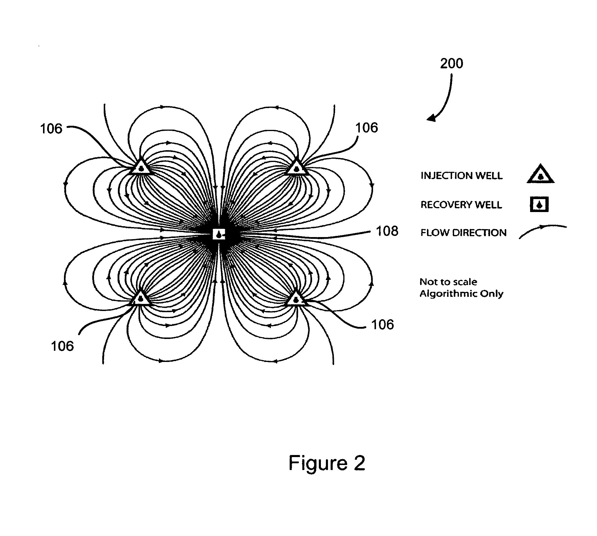
[0100]An apparatus consisting of a column of packed sand, a fluid vessel, a pressure cylinder and a collection device is used to conduct the experiments. The sand column is constructed using clear or black PVC tubing and wrapped in heat tape for temperature control, with control and measurement apparatus at the inlet and outlet. The sand pack was prepared using unwashed, unsorted, sacked commercial sand consistent with experimental standards. The column is initially saturated with ˜1% saline water for a minimum of one week to establish the initial solid-liquid wettability, and to remove entrained air prior to the initial displacement with hydrocarbon fluid.

[0101]The displacement and aging of the water-saturated column by hydrocarbon fluid yields a mixed wettability state. The injected solutions are placed into the pressurized fluid vessel and injected into the sand column. The displaced fluid volume is collected and measured by phase, oxidation / reduction potential eH, pH hydrocarbon...


PUM

PropertyMeasurementUnit
Electric potential / voltageaaaaaaaaaa
Flow rateaaaaaaaaaa

Abstract

The present electrolytic system and method for extracting components includes a means for providing a carrier fluid; a means for providing a pair of electrodes interposed by a permeable membrane to create a first channel and a second channel; a means for flowing the carrier fluid through the first and second channel; a means for applying a voltage to the pair of electrodes to produce a first ionized carrier fluid in the first channel and a second ionized carrier fluid in the second channel; a means for injecting at least one of the first ionized carrier fluid and the second ionized carrier fluid into the subsurface reservoir to release the components; and a means for recovering the at least one of the first ionized carrier fluid and the second ionized carrier fluid and the components from a subsurface strata or ex-situ mineral deposit.

Description

FIELD OF THE INVENTION[0001]This invention relates to the recovery and deposition of hydrocarbons, fluids, solid minerals, and other components in the subsurface or ex-situ by the direct introduction of a charged fluid, and more particularly to the recovery of hydrocarbons from geologic media.BACKGROUND OF THE INVENTION[0002]It is a problem in the field of fluid and solid mineral extraction to efficiently extract subsurface components in subsurface deposits, reservoirs, or fields. For example, the oil industry typically produces only about one-third of the original oil in place (“OOIP”) from a field before it is considered “depleted.” The termination of recovery operations from depletion is really driven by declining oil recovery until an economic limit is approached and the recovery operation is terminated or mothballed. Thus, the majority of oil remains un-recovered though discovered, identified and with direct physical access by existing wells. World oil demand is expected to jum...

Claims


Application Information

Patent Timeline
IPC IPC(8): E21B43/16
CPCE21B43/28E21B43/16
Inventor PETERS, MICHAEL J.FAULDER, DAVID D.
Owner STRATEGIC RESOURCE OPTIMIZATION
Learn More