
Laminated identification document

a technology of identification documents and laminates, applied in the field of laminated documents, can solve the problems of identity theft rampant, inability to verify one's true identity, and inability to meet the requirements of the identity verification process, so as to reduce the explosive laser force, increase the compatibility strength, and high cohesive strength

Active Publication Date: 2008-05-08
FELDMAN JOSEF
View PDF29 Cites 39 Cited by
  • Summary
  • Abstract
  • Description
  • Claims
  • Application Information

AI Technical Summary

Benefits of technology

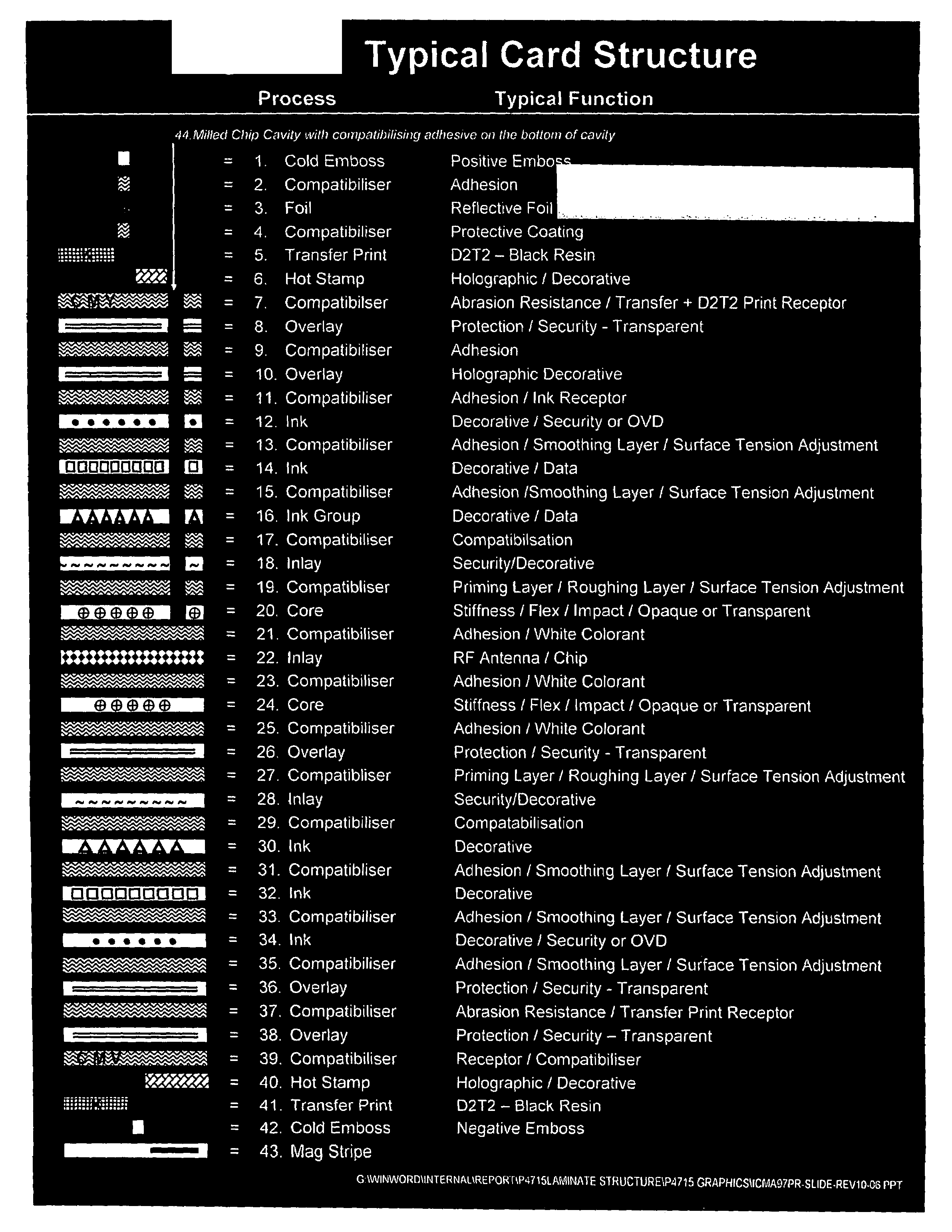
[0024]It is an object of this invention to use compatibilizing imaging materials that can be laser marked at lower power densities (less than one watt / micron) and still have very high cohesive strength. Thus by reducing the explosive laser force and increasing the cohesive strength of the compatibilised structure, one can create laser markable robust card and CD structures that will not delaminate or redeposit material in unwanted areas.
[0027]It is a further object of this invention, through the use of such compatibilized layer or layers in an identification card structure, to remedy certain problems associated with such card structures, in particular, the minimization or prevention of flex stresses that damage the card and / or the prevention of the card itself from cracking due to normal wear and tear.
[0028]It is a further object of this invention, through the use of such compatibilized layer or layers that replace the conventional chip adhesive in a smart card to prevent the smart card module from popping off the card when flexed, to minimize or prevent flex stresses that damage the card and / or to prevent the card itself from cracking due to normal wear and tear.
[0033]It is still another object of this invention, through the use of such compatibilized layer or layers, to obtain an identification card that has a high reflectivity in the visible region of 400-800 nm and has absorbency for a laser wavelength to permit marking of the opaque or reflective coated or laminated white or clear core with multi colored indica such as bar codes, photos and other biometric or data containing indicia. Preferably, the recording media is a holographic metallic layer and the imaging creates discontinuities in the metallic layer and does not interfere with the transmission of RF data to the antenna of a contactless card. The Holographic material may have tracks to help guide the LD write / read control mechanism similar to CD or DVD writing materials.

Problems solved by technology

Verifying one's true identity is an ever-increasing problem.
Identity theft is rampant, and stolen identities have even been used to facilitate terrorist attacks.
Computer networks and secure areas have been breached with misappropriated keys, passwords and codes.
The D2T2 printed cards are generally not durable enough for long life identity cards while the laser engraved cards are generally a one color print on a contrasting background.
The microporous core materials, such as Teslin® synthetic paper, however have some physical disadvantages in that it is structurally weaker than solid core materials and as a thermoplastic is easier to delaminate under heat.
Jones et al enumerates additional deficiencies and problems associated with conventional smart cards.
In the case of contact smart cards, some of these problems include the smart card module popping off the card when flexed, flex stresses that damage the smart card module, and / or the card itself cracking with normal wear and tear.
However, Polycarbonate is expensive, cannot be embossed and unless it is coated, is very sensitive to notch impact failure.
This means that if the surface is scratched, it can crack through the scratch.
A disadvantage of the Gunn and Schild coatings is that they are solvent-based coatings that include aggressive organic solvents and additionally are undesirable for environmental and work safety issues.
Thus, it is generally undesirable to use solvent systems in these type applications.
Such burn indicium makes alteration of data difficult or impossible to accomplish.
Such a solution, does not address the notch sensitivity of Polycarbonate and the possibility of cracking, nor does it address the need for OTC personalization in color using dye diffusion thermal transfer D2T2.
Pure Polycarbonate does not accept standard D2T2 printing.
Such a characteristic makes security documents made from such materials highly susceptible to security breaches and tampering.
There are thus serious deficiencies in the current structures involving susceptibility to thermal delamination and weakening of the physical structure by using solvent-based processes.

Method used


Image

  • Laminated identification document
  • Laminated identification document
  • Laminated identification document

Examples


example 1

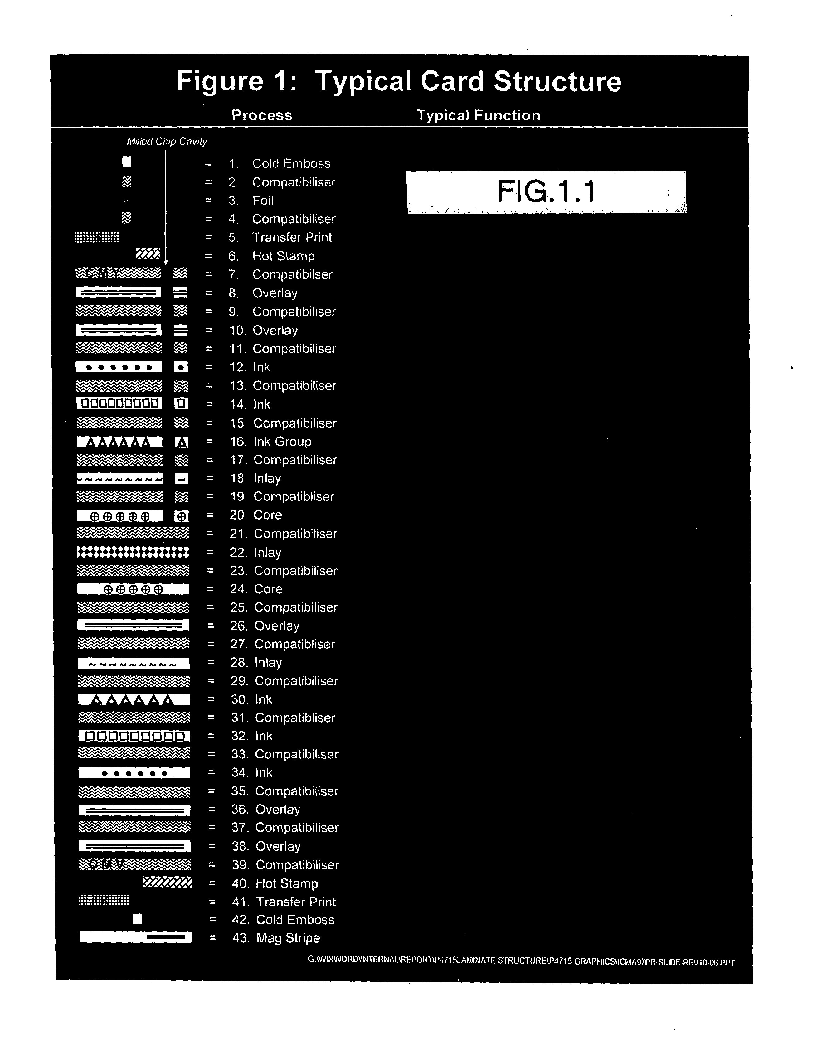
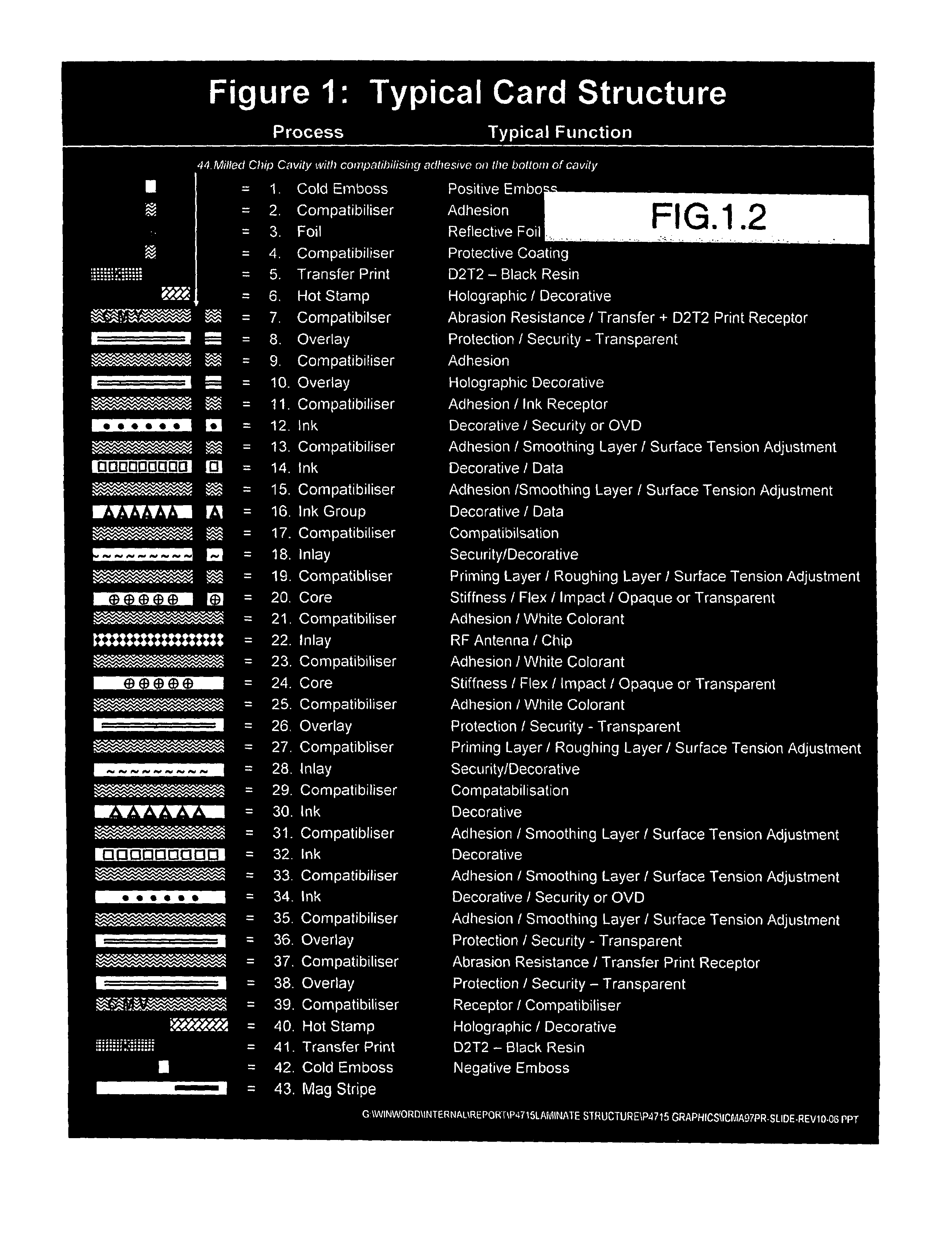
[0129]UV102 (FM Group), a formulated UV activated vinyl acrylate copolymer (hard material) concentration of 100% was used as the compatibilizer (FIG. 2, layer 11). Layer 12 was a lithographic print of Gans UV Black ink 100% density over core 20 in a patch of at least 1″×3″ to allow for peel tests. Peels were checked over both the UV Black and the unprinted white core. After UV-light exposure the material was brittle. When laminated with uncoated clear PVC overlay under condition Laminate 1 there was no adhesion between layers 10 and 20 for the ISO 90 degree peel test.

[0130]All peel data referred to herein are in accordance with this test. These tests were repeated with the overlay changed to Polyester (PET) and Polycarbonate(PC) with similar results.

LAYERComposition10Overlay (PVC or Polyester (PET) or Polycarbonate)11Compatibilizer UV 10212100% Black UV Ink (full bleed20Core (PVC, PET or PC)26Overlay (PVC or Polyester (PET) or Polycarbonate).

example 2

[0131]UV103 (FM Group) a formulated UV activated vinyl acrylate copolymer (soft material) concentration of 100% was used as the compatibilizer (FIG. 2, layer 11). After UV-light exposure the material was brittle. When laminated under condition Laminate 1 there was no adhesion between layers #10-#20

LAYERComposition10Overlay (PVC or Polyester (PET) or Polycarbonate)11Compatibilizer UV 10312100% Black UV Ink (full bleed20Core (PVC, PET or PC)26Overlay (PVC or Polyester (PET) or Polycarbonate).

Example 3

[0132]A mixture consisting of UV102 (FM Group) a UV activated vinyl acrylate copolymer (hard material) concentration of 50% and UV103 (FM Group) a UV activated vinyl acrylate copolymer (soft material) concentration of 50% was used as the compatibilizer (FIG. 2, layer 11). This material will be called UV104-5050

[0133]After UV-light exposure the material formed strong film. When laminated immediately with 1.8 mil PVC as Layer 10 under condition Laminate 1 there was 90 degree adhesion over w...

example 3

[0135]The same structures as Example 3 but an additional 5% of curing agent (C5) was added. There was 90 degree adhesion over white or UV black between layers 10 to 20 of 2.4 Newton's / mm more then 5 times the ISO bankcard requirement (0.45 Newton / mm). High adhesion was reached due to combination of UV curing and thermo curing processes.


PUM

PropertyMeasurementUnit
Nanoscale particle sizeaaaaaaaaaa
Fractionaaaaaaaaaa
Fractionaaaaaaaaaa

Abstract

A laminated identification document having a plurality of laminate layers and an identification image thereon. The document has a core laminate layer having an upper surface and lower surface, at least one surface of which is printed with a dot matrix pattern and at least one visually opaque or reflective laminate layer bonded to and overlaying the printed surface. Upon pitting the laminate layer portions, the dot matrix pattern printed on the core laminate is expopsed to thereby form the identifying image.A laser markable laminated identification document having a plurality of laminate layers wherein a compatibilising layer is bonded to adjoining laminate layers, the compatibilising layer includes an imaging material that can be laser marked.A laminated identification document having a plurality of laminate layers and an identification image thereon, wherein at least one laminate layer is a compatibilising layer.

Description

RELATED APPLICATIONS[0001]This application claims priority of provisional application U.S. Ser. No. 60 / 857,031 filed on Nov. 6, 2006.SPECIFICATION[0002]1. Field of the Invention[0003]The present invention relates to laminated documents that are required to be secure. More particularly, it relates to the laminated identification documents, passports, and smart cards and other similar type security documents.[0004]2. Background of the Invention[0005]Verifying one's true identity is an ever-increasing problem. Identity theft is rampant, and stolen identities have even been used to facilitate terrorist attacks. Computer networks and secure areas have been breached with misappropriated keys, passwords and codes.[0006]One conventional solution typically includes an identification document having a biometric indicium such as a photographic image or fingerprint of the authorized holder on the document protected from tampering by one or more security features.[0007]Another solution is what i...

Claims


Application Information

Patent Timeline
IPC IPC(8): B29C59/00B32B37/00B32B7/00B42D15/10G03C1/00
CPCB32B27/08Y10T156/10B32B2307/41B32B2307/416B32B2425/00B32B2519/00B42D2035/06B42D2035/14B44C1/005B44C1/22B42D25/41B42D25/43B42D25/00B42D25/45Y10T428/24802Y10T428/24B32B33/00B29C59/00B32B37/00B32B7/00
Inventor FELDMAN, JOSEFLIPKIN, ANATOLYPERSINKO, MARK M.
Owner FELDMAN JOSEF
Learn More