
Electrowetting device and varifocal lens, optical pickup device, optical recording/reproduction device, droplet operation device, optical element, zoom lens, imaging device, light modulating

a technology of optical pickup and varifocal lens, which is applied in the direction of variable capacitor, generator/motor, instruments, etc., can solve the problems of difficult to deposit uniform and thin dielectric film on liquid storage containers, and achieve high dielectric constant, easy and precise control of thickness, and reduced drive voltage to change the contact angle of liquid materials

Inactive Publication Date: 2008-05-01
SONY CORP
View PDF15 Cites 42 Cited by
  • Summary
  • Abstract
  • Description
  • Claims
  • Application Information

AI Technical Summary

Benefits of technology

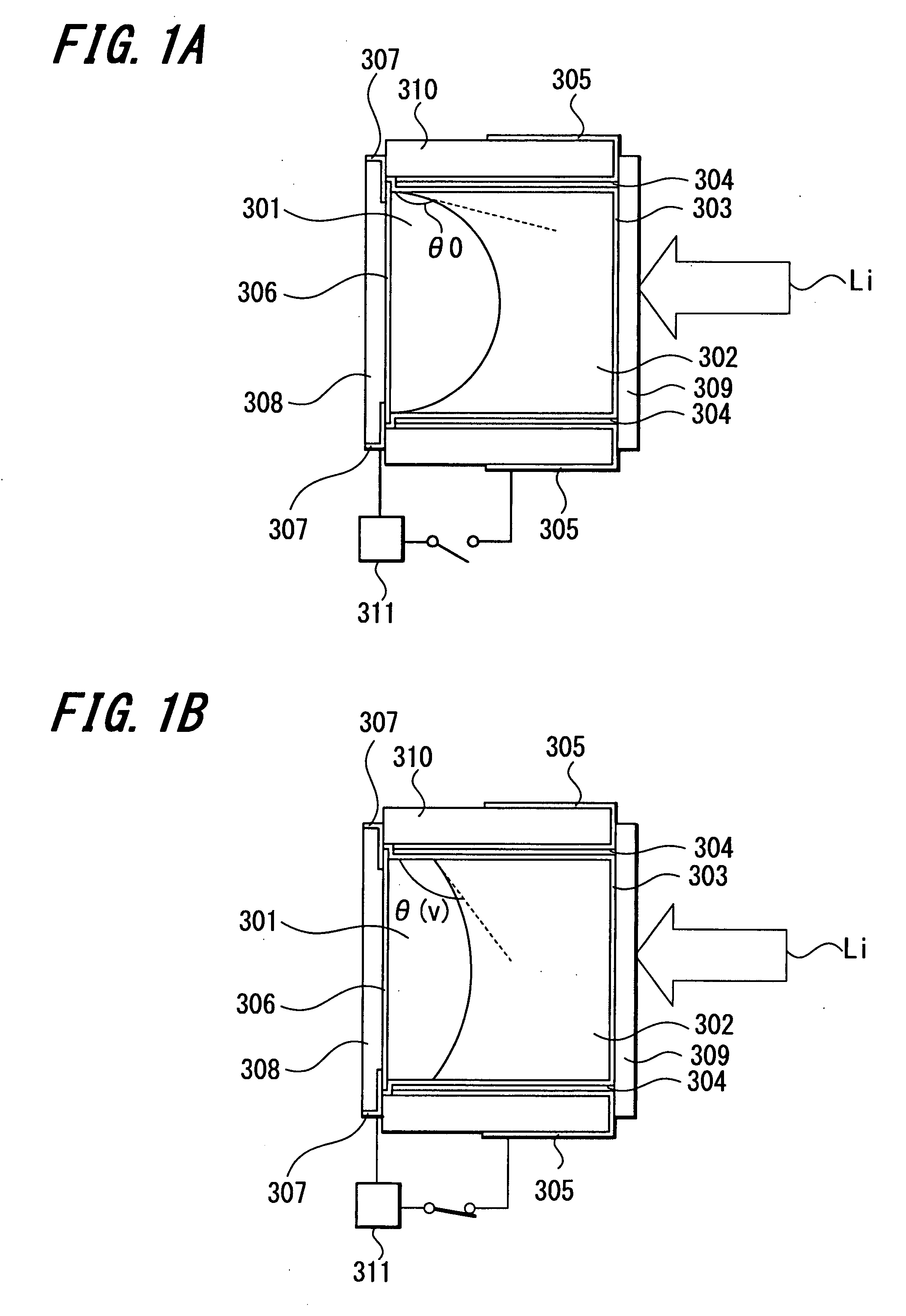
[0027] Specifically, as is clear from the formula (I), a change in the contact angle θ between the liquid material and the inner wall of the container by an electrowetting phenomenon occurs in direct proportion to the dielectric constant ∈ of the dielectric film times the drive voltage V squared and in inverse proportion to the thickness l of the dielectric film. Accordingly, drive voltage causing an equal change in focal length may be reduced by increasing the dielectric constant ∈ of the dielectric film and reducing the film thickness l.
[0031] In this situation, the present applicant has proposed a varifocal lens using a dielectric film obtained by anodizing an electrode and an optical device using the same in Japanese Patent Application No. 2005-106524 (filed on Apr. 1, 2005). The varifocal lens and the optical device are advantageous in that a dielectric film may be formed with an extremely small thickness using a film obtained by anodizing a metal such as tantalum or niobium; a drive voltage may be reduced due to an extremely high relative dielectric constant of the dielectric film; and the dielectric film may be deposited with a reduced variability in film thickness, so that a change in contact angle of an interface may be controlled with high precision.
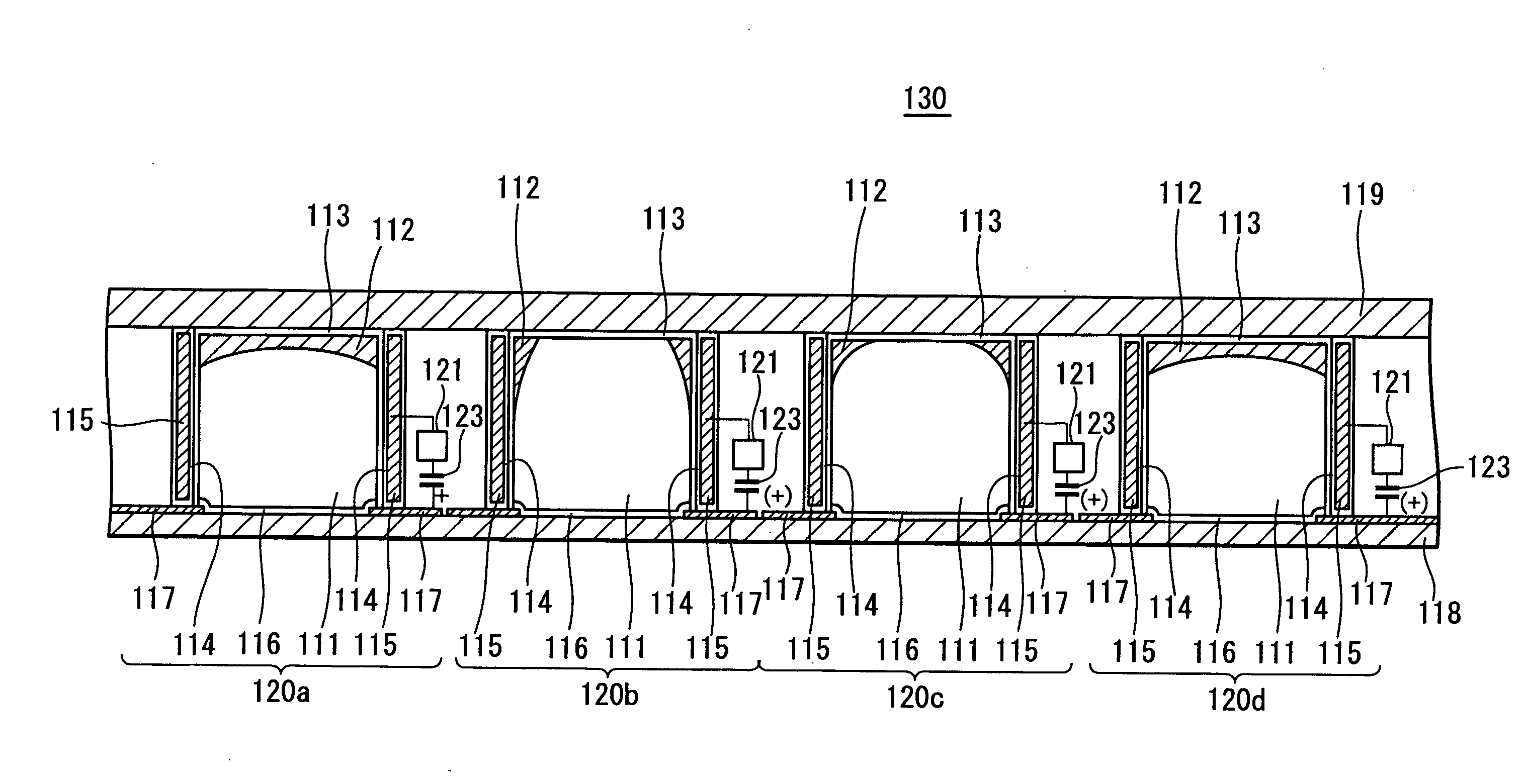
[0044] As described above, an electrowetting device according to an embodiment of the present invention and a varifocal lens, an optical pickup device, an optical recording / reproduction device, a droplet operation device, an optical element, a zoom lens, a light modulating device, and a display device using the same employs, as a dielectric film provided between a conductive or polar liquid material and an electrode, a metal oxide formed by anodizing the electrode. An anodized portion formed by the metal oxide may have a thickness easily and precisely controlled by controlling voltage applied during anodization.
[0045] More specifically, various materials providing oxides having a relatively high dielectric constant by anodization may be used such as valve metals such as aluminum and tantalum generating alumina and tantalum pentoxide films by anodization. Drive voltage to change a contact angle of a liquid material may be reduced using, as a dielectric film, an anodized portion having high insulating properties and a high dielectric constant and having a film thickness easily reduced.
[0048] On the contrary, an electrowetting device according to an embodiment of the present invention includes a capacitor, in addition to a voltage application unit, inserted between an electrode and a liquid material, so that the device may be non-polarized in its entirety and thus may be AC-driven. When the device is AC-driven, it is possible to avoid a gradual reduction in the effect of electrowetting phenomenon by DC-driving the device.

Problems solved by technology

This is because it is difficult to deposit a uniform and thin dielectric film on a liquid storing container forming the varifocal lens.

Method used


Image

  • Electrowetting device and varifocal lens, optical pickup device, optical recording/reproduction device, droplet operation device, optical element, zoom lens, imaging device, light modulating
  • Electrowetting device and varifocal lens, optical pickup device, optical recording/reproduction device, droplet operation device, optical element, zoom lens, imaging device, light modulating
  • Electrowetting device and varifocal lens, optical pickup device, optical recording/reproduction device, droplet operation device, optical element, zoom lens, imaging device, light modulating

Examples


first embodiment

[1] First Embodiment

[0083] First, an embodiment of a varifocal lens using an electrowetting device according to an embodiment of the present invention will be described with reference to schematic cross-sectional views of FIGS. 5A and 5B.

[0084] The varifocal lens 10 includes a container 9 having a cylindrical shape or the like and made of an insulating material; a conductive or polar first liquid material 11 stored in the container 9; and an insulating second liquid material 12 stored in the container 9. Materials both light transmissive, having different refractive indices, and not mixed with each other are selected as the first and second liquid materials 11 and 12. A difference in specific gravity is preferably small between the first liquid material 11 and the second liquid material 12 in forming the varifocal lens. When the difference in specific gravity is small, it is possible to suppress deformation of an interface shape due to vibration or gravity. However, this is not the...

second embodiment

[2] Second Embodiment

[0134] A varifocal lens according to an embodiment of the present invention as described above may be driven at significantly reduced voltage as compared with a varifocal lens of the related art, and therefore may be used for various optical devices in which a small varifocal lens may not used in the related art.

[0135] For example, the varifocal lens may be used as an aberration correcting element or a collimator lens having a variable magnification in an optical recording / reproduction device to perform recording and / or reproduction of various optical discs such as a CD (Compact Disc), DVD (Digital Versatile Disc), or BD (Blu-ray Disc®), and an optical pickup device for the optical recording / reproduction device.

[0136] In particular, in an optical recording / reproduction device using a multiple wavelength light source which is compatible to such various optical discs, it may be necessary to make a focal length of a collimator lens variable. A varifocal lens acco...

third embodiment

[3] Third Embodiment

[0146] An electrowetting device according to an embodiment of the present invention is not limited to an optical device through which light may pass such as the aforementioned varifocal lens, and may be used for various other devices utilizing a modification of a liquid material. Next, an example of a liquid operation device will be described as one example of the electrowetting device.

[0147] Development of microfluidic systems to perform predetermined treatment for a microsize continuous liquid flow is now in progress. There is a demand for development of microfluidic devices to realize sensors and analyzers called “chemistry-on-a-chip”, in particular. Such sensors and analyzers are also known as “Labs-On-a-Chip” (LoC) and micrototal analysis systems (1-TAS). Automated chip devices are formed using the microfluidic systems, so that it is possible to provide chemical (or biochemical) experimental instruments that may be operated at high speed and portable and ar...


PUM

PropertyMeasurementUnit
voltageaaaaaaaaaa
thicknessaaaaaaaaaa
dielectric constantaaaaaaaaaa

Abstract

Disclosed is an electrowetting device. The electrowetting device includes a conductive or polar liquid material, and an electrode applying voltage to the liquid material through a dielectric layer. In the electrowetting device, the dielectric layer is formed as an anodized portion made of a metal oxide formed by anodizing the electrode, and a voltage applying unit applying voltage between the electrode and the liquid material and a polar capacitor are placed between the electrode and the liquid material.

Description

CROSS REFERENCES TO RELATED APPLICATIONS [0001] The present invention contains subject matter related to Japanese Patent Application JP 2006-268216 filed in the Japanese Patent Office on Sep. 29, 2006, the entire contents of which being incorporated herein by reference. BACKGROUND OF THE INVENTION [0002] 1. Field of the Invention [0003] The present invention relates to an electrowetting device utilizing an electrowetting (electrocapillary) phenomenon, and a varifocal lens, an optical pickup device, an optical recording / reproduction device, a droplet operation device, an optical element, a zoom lens, an imaging device, a light modulating device, and a display device using the same. [0004] 2. Description of the Related Art [0005] Varioptic S.A. of France and Royal Philips Electronics N.V. of the Netherlands disclose varifocal lens devices, for example, as electrowetting devices utilizing electrowetting phenomena (see Japanese Unexamined Patent Application Publication (Translation of P...

Claims


Application Information

Patent Timeline
Patent Type & Authority Applications(United States)
IPC IPC(8): G02F1/01G02B1/06H02N2/02G11B7/135
CPCG02B3/14G02B26/005G11B7/13925G11B7/1378G11B7/1376G02B3/12
Inventor KATO, YOSHIAKIMAEDA, FUMISADA
Owner SONY CORP
Learn More