
Inkjet recording apparatus

a recording apparatus and inkjet technology, applied in the direction of printing, duplicating/marking methods, inks, etc., can solve the problems of difficult to avoid depositing interference and image quality degradation, and achieve the effects of preventing depositing interference, suppressing image disturbance, and preventing image quality degradation

Inactive Publication Date: 2008-01-24
FUJIFILM CORP
View PDF3 Cites 15 Cited by
  • Summary
  • Abstract
  • Description
  • Claims
  • Application Information

AI Technical Summary

Benefits of technology

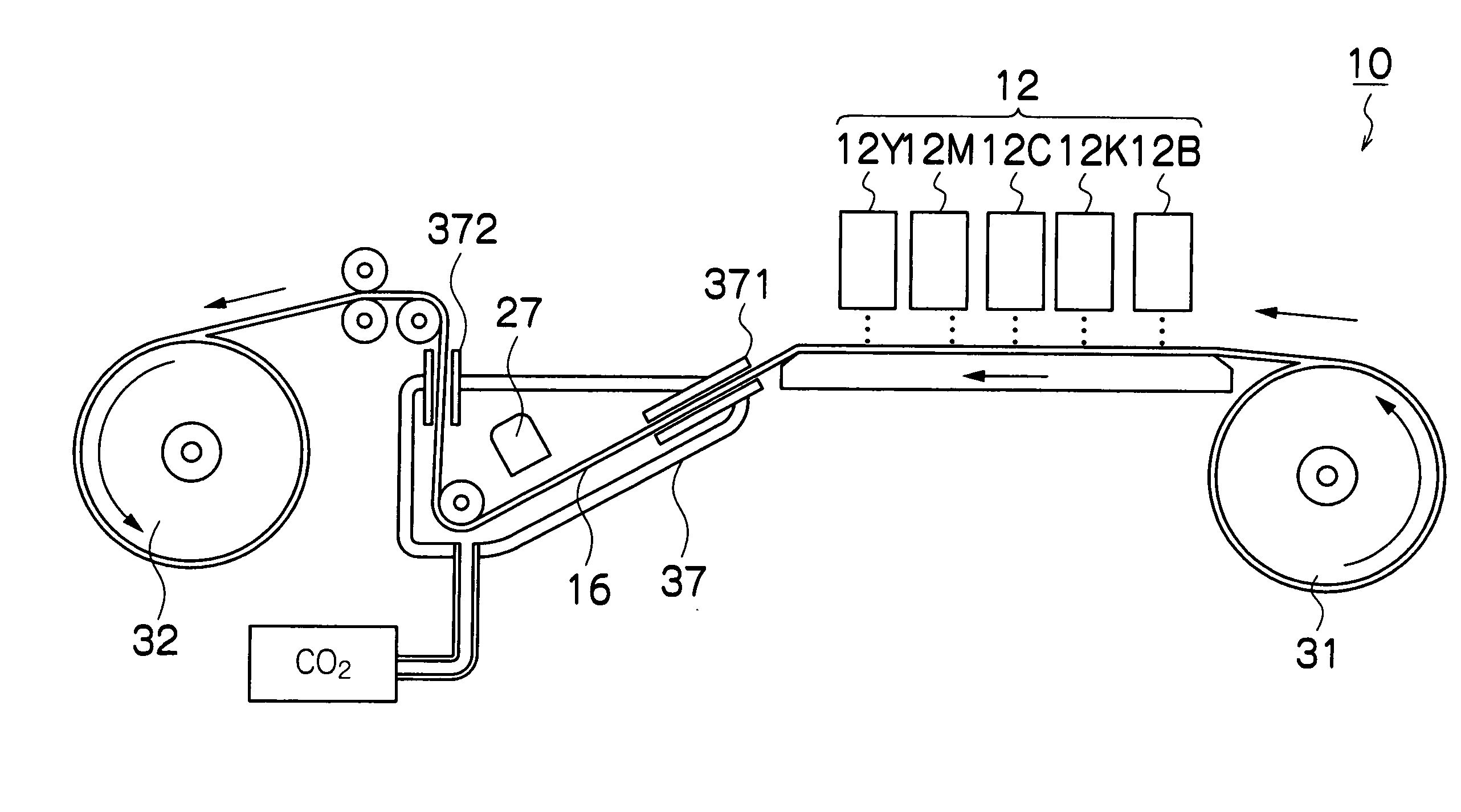
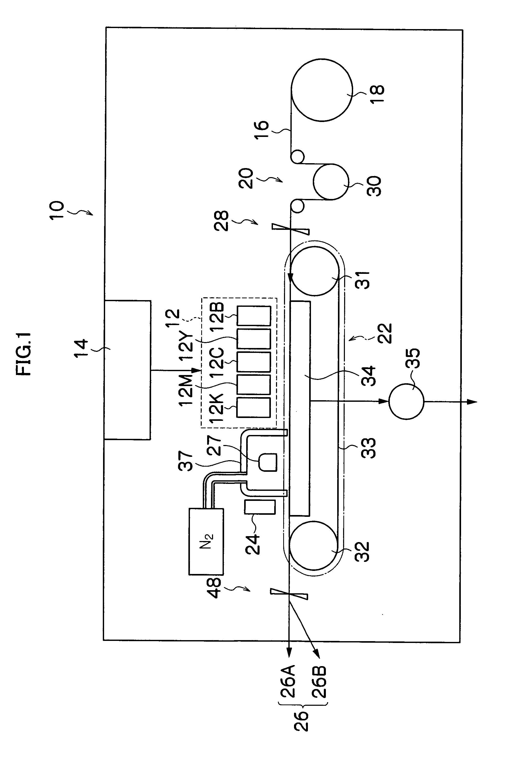
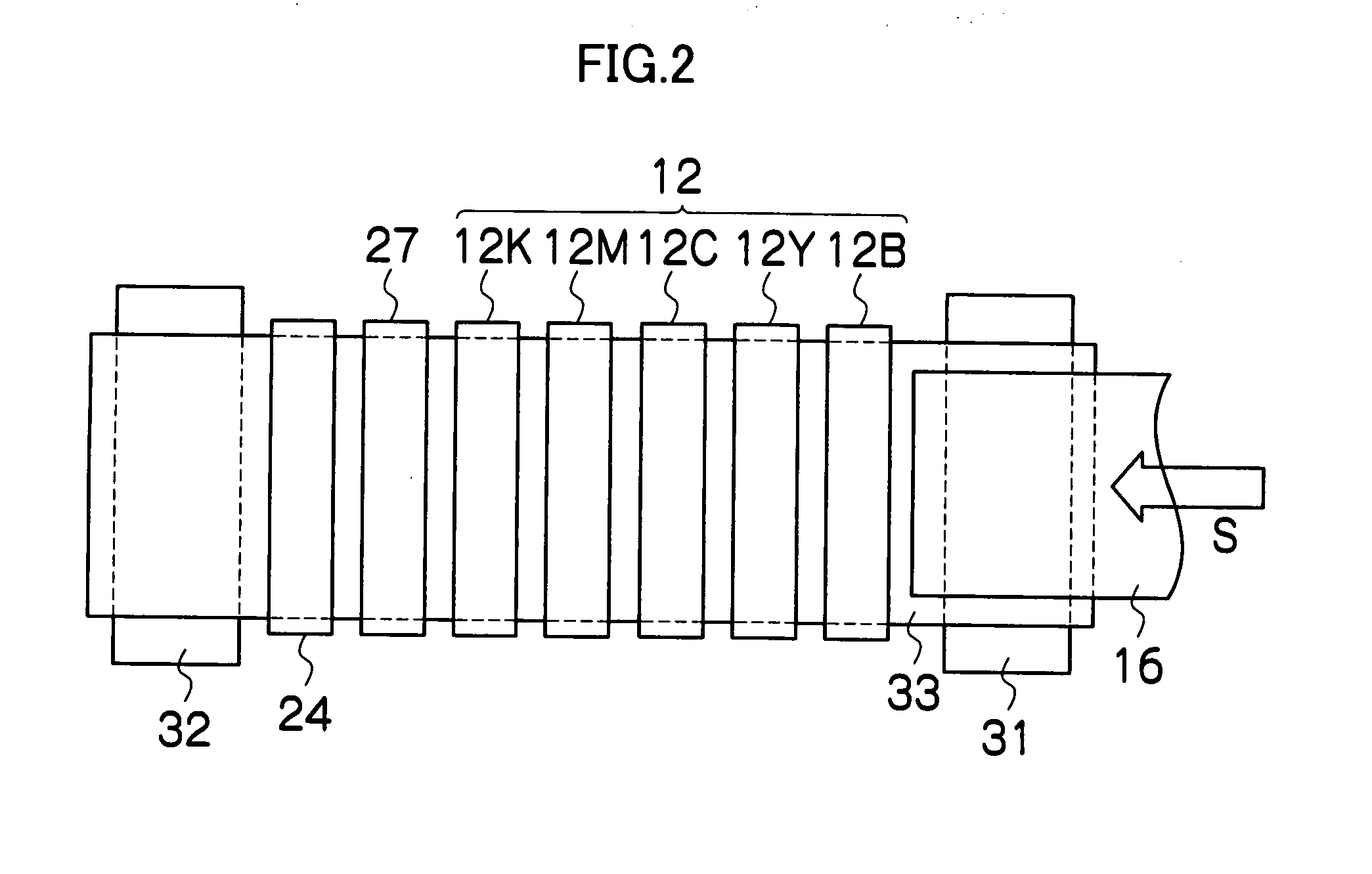
[0008]The present invention has been contrived in view of the aforementioned circumstances, an object thereof being to provide an inkjet recording apparatus which prevents the depositing interference between the ink droplets, while also being able to prevent the degradation of image quality caused by curing defects, the movement of the gravity center and the unintentional expansion of the ink dots.
[0012]In this aspect of the present invention, it is possible to prevent the degradation of image quality caused by curing defects, the movement of the gravity center and the unintentional expansion of the ink dots, while avoiding the depositing interference between the ink droplets by adopting the two-liquid system. Since the liquid application device deposits the first liquid (ink) containing coloring material in the form of droplets on the second liquid (treatment liquid) containing no coloring material or coloring material of not greater than 0.1 wt % that has been applied on the recording medium, then the coalescence of the deposited ink droplets on the recording medium is suppressed in comparison with the inkjet recording apparatus of one-liquid type. Since the polymerizable compound is cured by means of the electron beam radiated from the electron beam irradiation device, then it is possible to prevent the deterioration of image quality, such as the dot expansion or dot movement, or the like, caused by the effects of heat, in comparison with the case where the polymerizable compound is cured by the ultraviolet (UV) light. Since the acceleration voltage of the electron beam is 40 kV or greater, then the curing characteristics of the polymerizable compound are good and therefore it is possible to fix the coloring material on the recording medium, sufficiently. Moreover, since the acceleration voltage of the electron beam is no more than 60 kV, then it is possible to restrict heating of the recording medium, and therefore the degradation of image quality due to the effects of heat can prevented.
[0016]In this aspect of the present invention, since there is the relationship of γA>γB, then it is possible to prevent the degradation of image quality more effectively.
[0019]In this aspect of the present invention, since there is hardly any content of the material (solvent) which is not involved in polymerization, then the cured state of the first liquid and the second liquid is even more satisfactory and the disturbance of the image can be suppressed yet further.
[0020]According to the present invention, it is possible to prevent the depositing interference between the ink droplets, as well as being able to prevent the degradation of image quality caused by curing defects, dot expansion, or movement of gravity center of dot.

Problems solved by technology

In the inkjet recording apparatus of one-liquid type which uses the radiation-curable ink, it is difficult to avoid depositing interference (i.e., coalescence of ink droplets on the recording medium).
However, in the case where an ultraviolet light source (such as a metal halide lamp) is used as the radiation source for curing the ink, although it is possible to prevent the depositing interference as described above, ink dots are liable to float and move on a film of treatment liquid, and there may arise problems that: the gravity centers of the ink dots move due to the heating of the recording medium when irradiated with the ultraviolet light; the ink dots are unintentionally expanded; and consequently, the image quality is degraded due to the movement of the gravity center or the unintentional expansion of the ink dots.

Method used


Image

  • Inkjet recording apparatus
  • Inkjet recording apparatus
  • Inkjet recording apparatus

Examples


example 1

Practical Example 1

[0165]Experiments were carried out under conditions shown in FIG. 8, in order to determine the appropriate acceleration voltage for the electron beam in a case where two liquids, namely, liquid A (ink) and liquid B (treatment liquid), are deposited onto a recording medium and an electron beam is used as curing radiation.

[0166]In FIG. 8, comparative examples under conditions 1 to 9, 13 and 14 are listed. In conditions 1 and 2, ultraviolet (UV) light was used as a curing radiation. In conditions 3 to 8, treatment liquid was not deposited on the recording medium and only ink was deposited. In conditions 9, 13 and 14, two liquids, namely, treatment liquid and ink, were deposited and an electron beam (EB) was used as a curing radiation, but the acceleration voltage of the electron beam was out of the preferable range (40 kV to 60 kV).

[0167]In contrast to these comparative examples (conditions 1 to 9, 13 and 14), conditions 10 to 12 are practical examples of the present...

example 2

Practical Example 2

[0190]Experiments were carried out under conditions shown in FIG. 9, in order to determine the appropriate relationship between the surface tension of the ink and the surface tension of the treatment liquid, in the case where two liquids, namely, liquid A (ink) and liquid B (treatment liquid), were deposited on the recording medium and the electron beam was used as curing radiation.

[0191]In FIG. 9, conditions 1, 4 and 5 relate to comparative examples, and conditions 2, 3 and 6 relate to practical examples of the present invention.

[0192]In practical example 2, liquids A1 and A2 were prepared as the ink, and liquids B2, B3 and B4 were prepared as the treatment liquid. The compositions of the liquids A1, A2, B2, B3, and B4 are as follows.

[0193]Liquid A1: (surface tension 34.4 mN / m)[0194]bifunctional monomer (HDDA): 92 wt %,[0195]hexafunctional monomer (DPCA60): 5 wt %,[0196]pigment: 3 wt %

[0197]Liquid A2: (surface tension 31.2 mN / m)[0198]bifunctional monomer (HDDA): ...


PUM

PropertyMeasurementUnit
Acceleration voltageaaaaaaaaaa
Surface tensionaaaaaaaaaa

Abstract

The inkjet recording apparatus which forms an image on a recording medium by applying a first liquid containing coloring material and a second liquid containing no coloring material or the coloring material of not greater than 0.1 wt %, on the recording medium, includes: a liquid application device which applies the second liquid on the recording medium and then ejects droplets of the first liquid toward the second liquid applied on the recording medium; and an electron beam irradiation device which radiates an electron beam on the first liquid and the second liquid on the recording medium, wherein: at least one of the first liquid and the second liquid contains a polymerizable compound which is polymerized when irradiated with the electron beam; and the electron beam irradiation device radiates the electron beam at an acceleration voltage of 40 kV through 60 kV.

Description

BACKGROUND OF THE INVENTION[0001]1. Field of the Invention[0002]The present invention relates to an inkjet recording apparatus of two-liquid type which records an image on a prescribed recording medium by using a first liquid containing a coloring material, and a second liquid containing no coloring material or a small amount of coloring material to prevent depositing interference.[0003]2. Description of the Related Art[0004]An inkjet recording apparatus of one-liquid type has been known, which uses an ink of radiation-curable type which is cured when irradiated with radiation, such as ultraviolet (UV) light, an electron beam (EB), or the like. Here, the electron beam (EB) is a flow of electrons imparted with a large energy by being accelerated by means of a high voltage.[0005]Japanese Patent Application Publication Nos. 2004-18656 and 2004-42465 disclose that an ink of one-liquid type that contains a pigment and a radiation-polymerizable monomer, which is curable by irradiation of ...

Claims


Application Information

Patent Timeline
IPC IPC(8): B41J2/015B41J2/145B41J2/01B41M5/00C09D11/00C09D11/322C09D11/324C09D11/326C09D11/328C09D11/38
CPCB41J2/2114B41J11/007B41J11/002B41J11/00216B41J2002/012B41J2/14233B41J2002/14459B41J2202/21
Inventor KADOMATSU, TETSUZOMAENO, YUTAKAMAKUTA, TOSHIYUKIUMEBAYASHI, TSUTOMU
Owner FUJIFILM CORP
Learn More