
Medical Device Applications of Nanostructured Surfaces

Active Publication Date: 2007-12-06
RGT UNIV OF CALIFORNIA +1
View PDF61 Cites 217 Cited by
  • Summary
  • Abstract
  • Description
  • Claims
  • Application Information

AI Technical Summary

Benefits of technology

[0008] The plurality of nanostructured components enhance one or more of adhesion, non-adhesion, friction, patency or biointegration of the device with one or more tissue surfaces of a body of a patient depending on the particular application of the device. The nanofibers (or other nanostructured components) on the surfaces of the medical device can optionally be wholly or partially coated with any number of materials including biocompatible polymers, which may be flowable (e.g., for injecting into the body). The polymer can protect the wires during insertion into the body of a patient, and then, in certain embodiments, can be soluble to expose the nanowires in situ for their intended application (e.g., adhesion, cellular integration, and the like). In one embodiment, the nanowires can be embedded (e.g., potted) in a plastic or polymer matrix material such as PTFE, and then the material can be partially etched or otherwise partially removed (either in situ or ex situ) such that the plastic or polymer matrix can protect most of the length of each nanofiber, leaving only portions of the nanowires such as their ends exposed for their desired intended application (e.g., adhesion, cellular integration, anti-bifouling etc.). Thus, for example, nanostructures such as nanotubes and nanowires can be easily applied to low melting temperature plastics and polymers for various medical device applications as described more fully herein. Polymer chains can be formed in situ in a dilute aqueous solution primarily consisting of a monomer and an oxidizing agent. In one embodiment the polymer is created in the solution and subsequently spontaneously adsorbed onto the nanofiber surfaces as a uniform, ultra-thin film of between approximately 10 to greater than 250 angstroms in thickness. UV initiated polymerization can also be used to perform polymerization or any other suitable method can be used as would be known in the art. In one preferred embodiment of the present invention nanofibers are coated with fibrinogen and / or fibrin, and there is a second coating comprising a biocompatible polymer thereon, e.g. for wound dressings.
[0029] In another embodiment of the present invention, a drug delivery device coated with nanowires (including nanofibers, nanotubes, nanorods, nanoribbons etc.) is disclosed, wherein the nanowires, because of their gecko-like adhesive properties, impart improved adhesive or frictional interaction with tissue or mucus by virtue of increased Van der Waals interactions arising from their increased surface area, and / or due to entanglement of the nanowires in the cellular / extracellular matrix. The nanowires can be made of a number of different biocompatible materials (e.g., Si, SiO2, ZnO, TiO2, etc.) which are non-toxic and easily resorbed or expelled from the device. The drug delivery device to which the nanowires are attached could be a designed drug carrier, a porous bead or any other device capable of delivering a drug to the desired site in vivo. In one exemplary embodiment, a drug delivery device coated with nanowires can be used to increase the residence time (and / or orientation) of the device in the small intestine which can provide a platform to target the delivery of drugs to the location at which they are most efficacous, thereby improving the pharmokinetics of the attached drugs. The drug delivery device with coated nanowires can be used to achieve targeted drug delivery at several other locations within the body for localized treatment of a variety of diseases including cancer and other diseases.

Problems solved by technology

Such infections can also result in illness, long hospital stays, or even death.
However, despite advances in sterilization and aseptic procedures as well as advances in biomaterials, bacterial and other microbial infection remains a serious issue in the use of medical implants.
Unfortunately, such infections are often resistant to innate immune system responses as well as to conventional antibiotic treatments.
It will be appreciated that such infections are problematic not just in treatment of humans, but also in treatment of a number of other organisms as well.

Method used


Image

  • Medical Device Applications of Nanostructured Surfaces
  • Medical Device Applications of Nanostructured Surfaces
  • Medical Device Applications of Nanostructured Surfaces

Examples


example i

i) Osteoblast Culture

[0391] Human fetal osteoblasts, designated hFOB 1.19 (American Type Culture Collection (ATCC), Manassas, Va.), were used for cell adhesion studies. This cell line was obtained from a spontaneous miscarriage and transfected with a temperature-sensitive mutant gene of SV40 large T antigen. The cells were programmed to proliferate at 34° C. and differentiate only when the temperature is raised to 39° C. Cells with passage 10 were used in all experiments. The medium used for growing osteoblasts consisted of 1:1 ratio of DMEM:F12 (Invitrogen Corp.) with 10% fetal bovine serum (Sigma-Aldrich) and 0.3 mg / mL of G418 sulfate powder (ATCC). The medium was changed every 2-3 days, and the subculture was done at a ratio of 1:4.

ii) Osteoblast Seeding

[0392] Different nanowire surfaces along with control (reference) surfaces (e.g., quartz) were placed in wells of 12-well plates and were placed under ultraviolet lights in a biological hood for 24 hours. They were then soaked ...

example ii

i) Materials and Methods

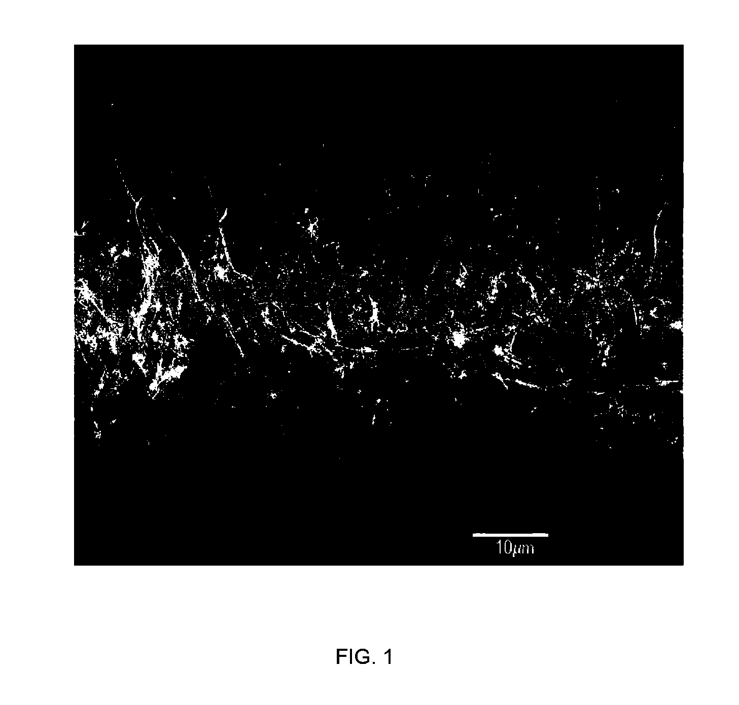
[0401] Each cell type was obtained from rats and was used as primary cells (used directly after isolation). Cells were seeded simultaneously at 3,500 cell / cm2 onto the materials and were cultured under standard conditions for 4 hours. The nanowire surfaces used in this study were prepared by growing nanowires from 40 nm gold colloids deposited onto poly-1-lysine coated titanium coupons (1 cm2) (Alfa Aesar, Ward Hill, Mass.) for 30 minutes at 480° C. The final grown nanowires were approximately 5-20 um long and 40 nm in diameter. Each cell type was fluorescently stained prior to seeding to assist in distinguishing each cell type after the adhesion experiment. After 4 hours, cells were then fixed and counted. Each experiment was done in triplicate and repeated at three separate times for statistical significance.

ii) Results and Discussion

[0402] The results of this competitive adhesion assay showed significantly more competitive adhesion after 1 day (FIG. 13A...

example iii

Synthesis of Nanowires on Nitinol Substrate

[0403] Following removal of organic residue from the Nitinol substrate surface (e.g., the surface is plasma cleaned with oxygen to remove any organics on the surface), the substrate is then placed in a CVD furnace in which it undergoes an approximate 30 minute run at approximately 480° C. to give a 6 to 10 nanometer conformal layer of microcrystalline silicon. The silicon coated material is then coated with an organic, chemical solution such as polylysine to ensure that the silicon surface is positively charged so that the gold colloid will adhere to the silicon coated surface. After the polylysine has been coated to the silicon coated surface, a liquid solution of gold colloid is deposited on the substrate for use as a catalyst within the subsequent chemical vapor deposition step. Selection of the colloid diameter is chosen based on the desired wire diameter size. The negatively charged gold colloid adheres to the positively charged surfa...


PUM


Abstract

This invention provides novel nanofiber enhanced surface area substrates and structures comprising such substrates for use in various medical devices, as well as methods and uses for such substrates and medical devices. In one particular embodiment, a method of administering a composition to a patient is disclosed which comprises providing a composition-eluting device, said composition-eluting device comprising at least a first surface and a plurality of nanostructures attached to the first surface, and introducing the composition-eluting device into the body of the patient.

Description

CROSS-REFERENCE TO RELATED APPLICATIONS [0001] This application is a continuation-in-part of U.S. patent application Ser. No. 11 / 330,772, filed Jan. 12, 2006, which is a continuation-in-part application of U.S. patent application Ser. No. 11 / 090,895 filed Mar. 24, 2005, which claims priority as a continuation-in-part of U.S. patent application Ser. No. 10 / 902,700 filed Jul. 29, 2004, which claims priority to U.S. Provisional Patent Application Ser. No. 60 / 549,711, filed Mar. 2, 2004. This application also claims priority as a continuation-in-part application of U.S. patent application Ser. No. 10 / 828,100, filed Apr. 19, 2004, which is a continuation-in-part of U.S. patent application Ser. No. 10 / 661,381, filed Sep. 12, 2003, which claims priority to U.S. Provisional Patent Application No. 60 / 463,766, filed Apr. 17, 2003; and as a continuation-in-part of U.S. patent application Ser. No. 10 / 833,944, filed Apr. 27, 2004, which claims priority to U.S. Provisional Application Ser. No. 60...

Claims


Application Information

Patent Timeline
IPC IPC(8): A61M37/00
CPCA61L27/54A61L29/16A61L2400/12A61L2300/622A61L31/16Y10S977/762Y10S977/902Y10S977/906Y10S977/742Y10S977/722
Inventor DESAI, TEJALDANIELS, R. HUGHSAHI, VIJENDRA
Owner RGT UNIV OF CALIFORNIA
Learn More