Small electron gun
a small electron gun and electron gun technology, applied in the field of electron gun, can solve the problems of limiting the downsizing of the ion pump, the inability to substantially keep a high vacuum pressure, and the difficulty of downsizing the ion pump, and achieve the effect of high vacuum pressur
- Summary
- Abstract
- Description
- Claims
- Application Information
AI Technical Summary
Benefits of technology
Problems solved by technology
Method used
Image
Examples
first embodiment
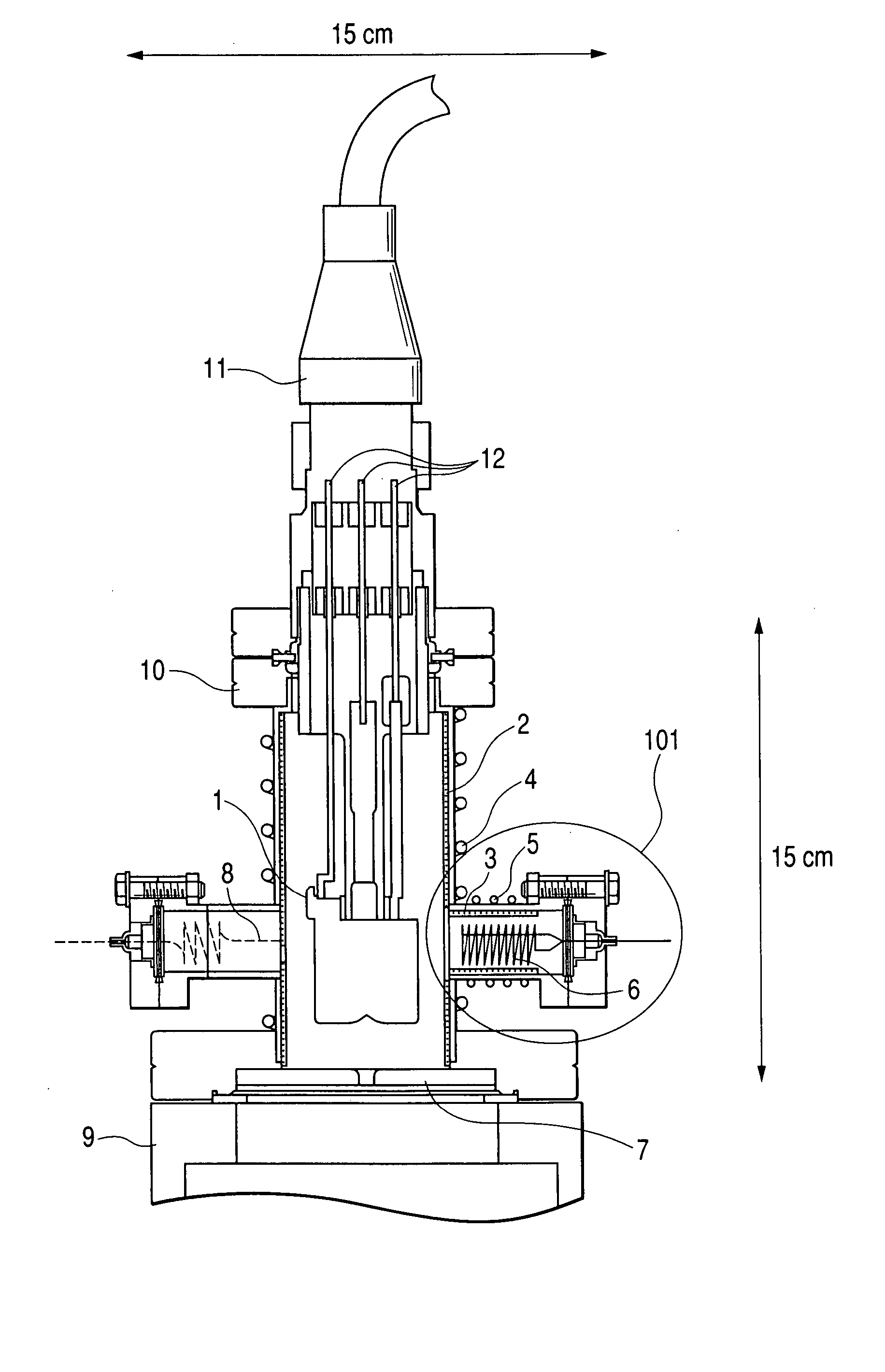
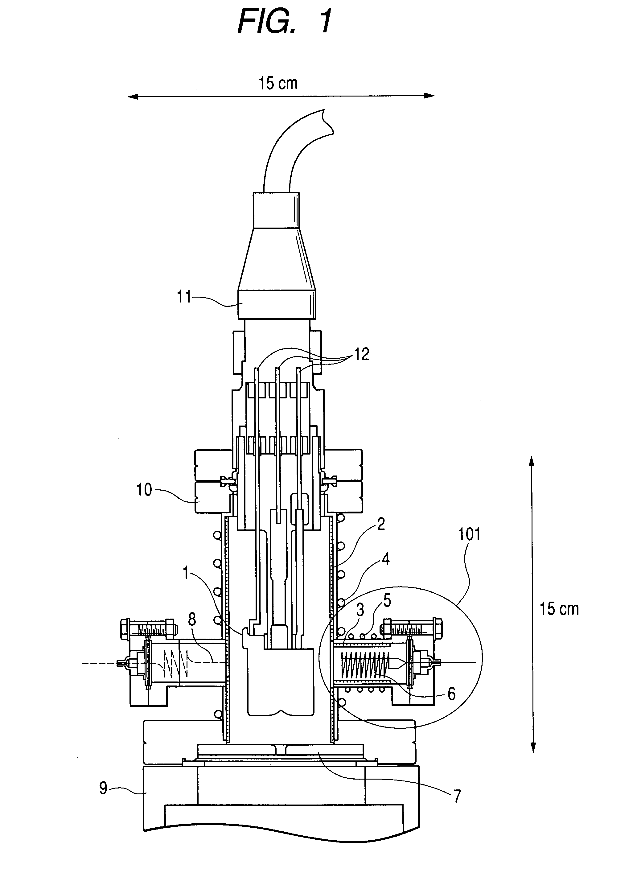
[0033]FIG. 1 shows a configuration of an electron gun of this embodiment. An electron source uses a thermal-field-emission electron gun (TFE) 1. The electron source 1 is set to the flange of an ICF 70 [WHAT IS “ICF 70”->It's a standard of flange used in a vacuum industry] and connected with an introduction terminal 12 to an electrode (suppressor, drawer, or chip) (not shown). The electron source 1 is inserted into and fixed to an electron-gun column 10.
[0034] The inside diameter of this column is approximately 37 mm. The column 10 has a sheeted nonevaporative getter pump 2 along the inside diameter. The nonevaporative getter pump 2 is activated when overheated to take in air. Therefore, a first heater 4 is set to the outside of the electron-gun column 10. This embodiment uses the heater 4 by winding a sheath heater on the electron-gun column 10. Note that a nonevaporative getter-pump heating device may be set in the vacuum vessel, in other words, the electron-gun column 10. A therm...
second embodiment
[0043] This embodiment describes the electron gun, described in the first embodiment, as applied to a scanning electron microscope.
[0044]FIG. 3 shows a schematic configuration of the scanning electron microscope of this embodiment. From the viewpoint of being advantageous for downsizing, every electronic optical system used in this embodiment uses a small electronic optical system constituted by an electrostatic lens. In FIG. 3, an electron beam 18 field-emitted from a field-emission electron gun 17 is thinly converged by electric fields formed between electrodes of an electrostatic lens set below the electron gun 17 and applied onto a sample 25. The electrostatic lens comprises a third lens electrode 19, a second lens electrode 20, and a first lens electrode 21.
[0045] At the same time, the electron beam 18 is deflected in the internal space of the second lens electrode 20 by a deflector 24 to two-dimensionally scan the surface of the sample 25. Moreover, to align the optical axis...
third embodiment
[0051] This embodiment describes the electron gun, described in the first embodiment, as applied to an electron-beam drawing apparatus. To provide a pattern drawing function for the small scanning electron microscope described in the second embodiment, the microscope may be used as an electron-beam drawing apparatus.
[0052]FIG. 4 is a schematic diagram of an electron-beam drawing apparatus of the third embodiment. It is possible to draw a pattern having a resolution of 6 nm on a resist film applied onto a sample 31 by sequentially reading data from a pattern record control device 30, previously storing the data for the layout of a pattern and the like, and deflecting an electron beam 18 by a deflector 24 so as to form the pattern. Moreover, it is possible to detect the position of a pattern to be drawn by detecting a secondary electron beam 33 generated from a region nearby a positioning mark, not shown, by a secondary electron detector 26.
[0053] Because this embodiment uses an acc...
PUM
 Abstract
Description
Claims
Application Information
 - R&D
- Intellectual Property
- Life Sciences
- Materials
- Tech Scout
- Unparalleled Data Quality
- Higher Quality Content
- 60% Fewer Hallucinations
Browse by: Latest US Patents, China's latest patents, Technical Efficacy Thesaurus, Application Domain, Technology Topic, Popular Technical Reports.
© 2025 PatSnap. All rights reserved.Legal|Privacy policy|Modern Slavery Act Transparency Statement|Sitemap|About US| Contact US: help@patsnap.com


