Charged particle beam writing method and apparatus
a charge particle and pattern technology, applied in the field of charge particle beam pattern writing method and apparatus, can solve the problem of uneven distribution of finished size of written pattern, and achieve the effect of higher accuracy
- Summary
- Abstract
- Description
- Claims
- Application Information
AI Technical Summary
Benefits of technology
Problems solved by technology
Method used
Image
Examples
embodiment 1
[0036]In each embodiment below, an explanation will be given of an arrangement using an electron beam as one example of the charged particle beam. Note that the charged particle beam should not exclusively limited to the electron beam and may alternatively be a beam using other charged particles, such as an ion beam or else.
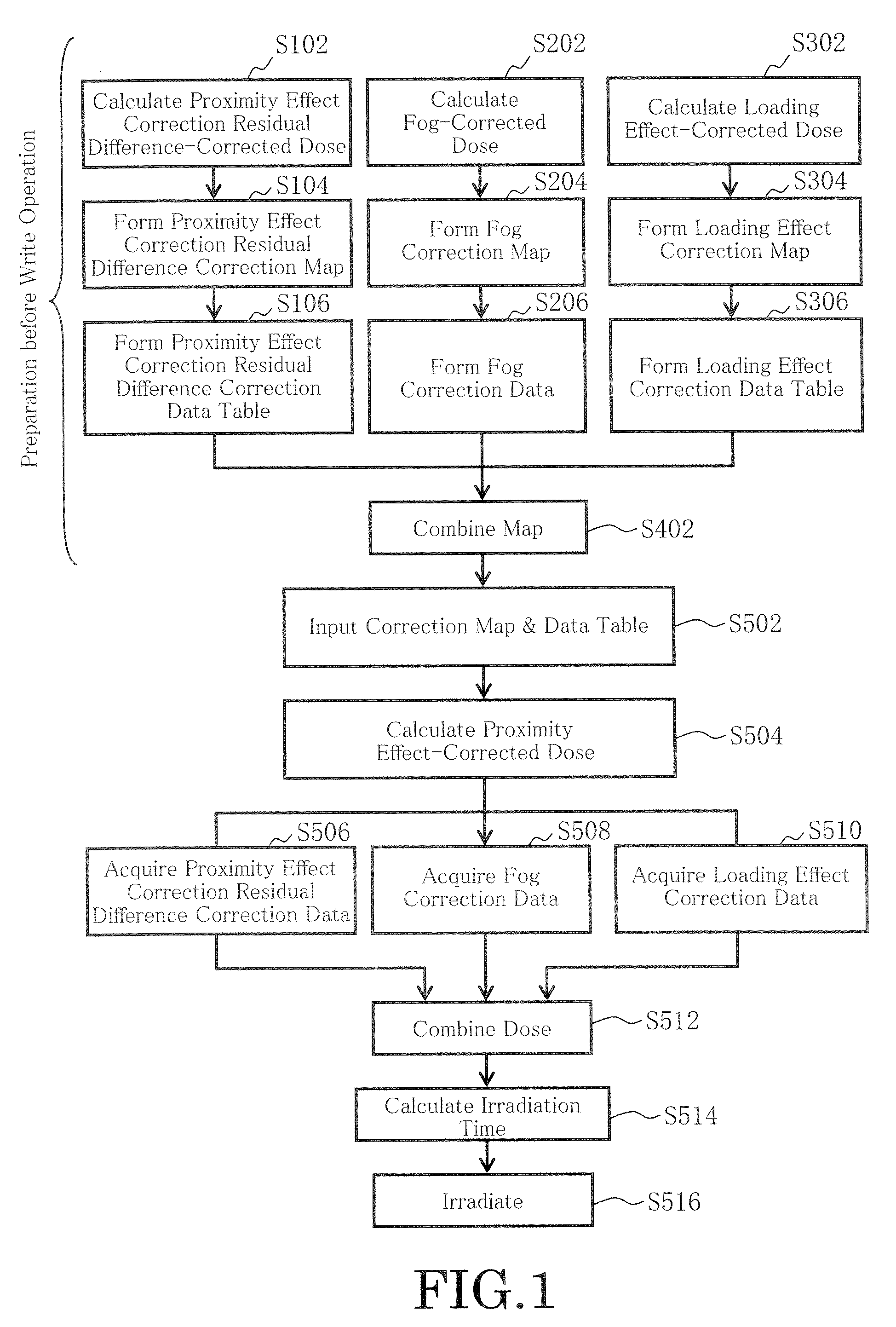
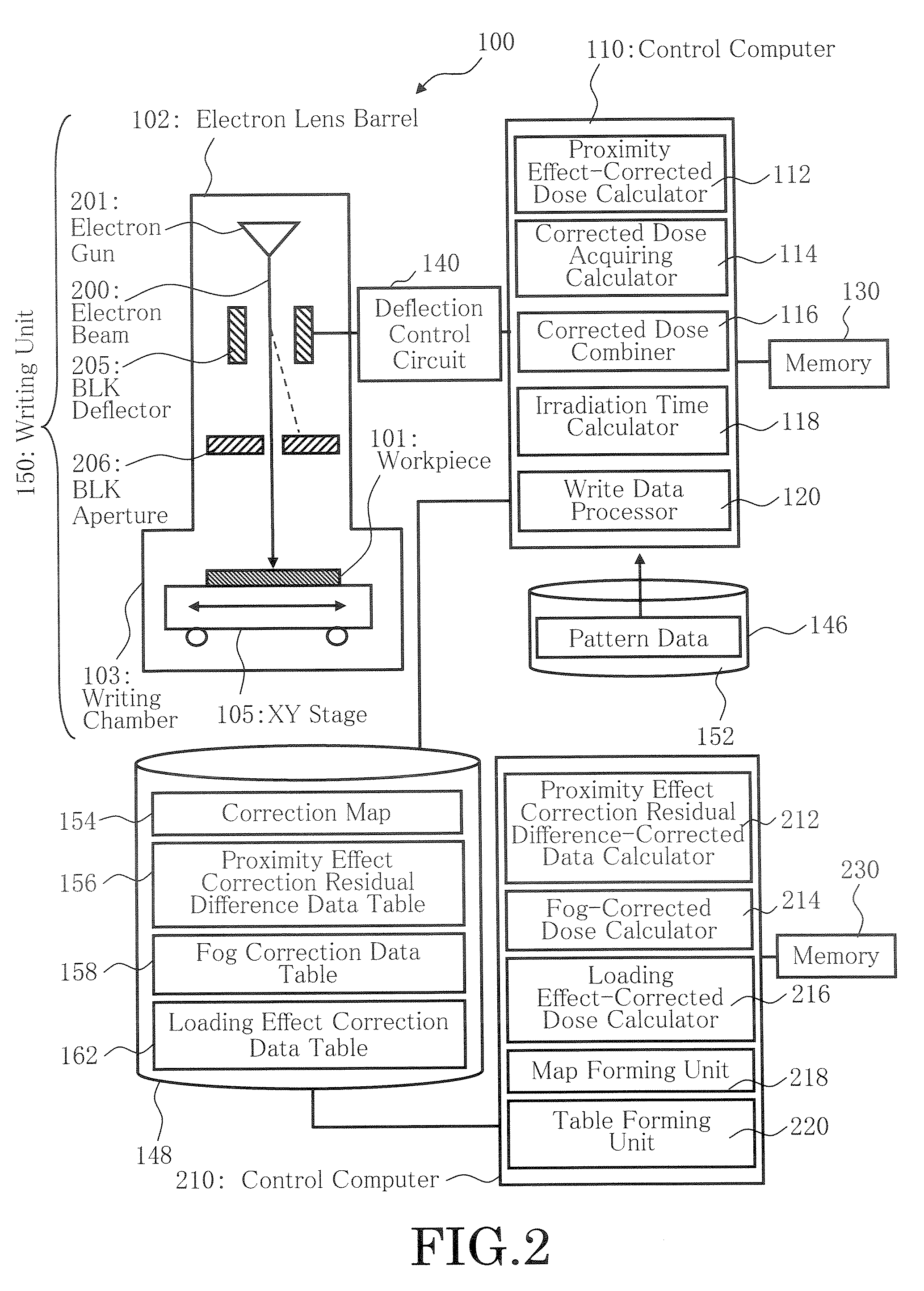
[0037]Also note that in an embodiment 1, in order to achieve the proximity effect correction and further correct the above-stated proximity effect correction residual difference and the fogging plus the loading effect, an entire plane of a processed surface of a workpiece such as a mask to be used in the manufacture of semiconductor devices is partitioned into mesh-shaped small regions with each side of about 1 mm for example (three kinds of regions—i.e., a proximity effect correction residual difference mesh region, fog correction mesh region and a loading effect correction mesh region—are set to have the same size because of the use of a correction map to be la...
embodiment 2
[0142]If the fog correction by means of the above-stated embodiment 1 is complete, then a distribution of resultant in-plane sizes after development becomes uniform. However, there is a case where a correction residual difference exists due to irregularities of the development and approximation used in calculations or the like. In an embodiment 2, an explanation will be given of a case where a fog correction residual difference dose DR(x,y) is further added as a parameter of the correction residual difference-corrected dose in the embodiment 1.
[0143]FIG. 17 is a diagram showing main part of a flow chart of an electron beam writing method in the embodiment 2.
[0144]In FIG. 17, the electron beam writing method performs a preparation process prior to an electron beam writing operation and an electron beam writing operation process. As the preparation process prior to the electron beam writing operation, it performs exemplary processes including a proximity effect correction residual dif...
embodiment 3
[0157]If the loading effect correction by means of the above-stated embodiment 1 is complete then the resulting size distribution after etching becomes uniform. However, there is a case where a correction residual difference exists due to the irregularity of an etching gas(es). In an embodiment 3, an explanation will be given of a case where a loading effect correction residual difference P(x,y) is further added as a parameter for correcting the correction residual difference in the embodiment 1.
[0158]FIG. 20 is a diagram showing main part of a flowchart of an electron-beam pattern writing method in the embodiment 3.
[0159]In FIG. 20, the electron beam writing method performs a preparation process before an electron beam writing operation and an electron beam writing operation process. As the preparation process before the electron beam writing operation, it performs exemplary processes including a proximity effect correction residual difference-corrected dose calculation step S102, ...
PUM
 Abstract
Description
Claims
Application Information
 - R&D
- Intellectual Property
- Life Sciences
- Materials
- Tech Scout
- Unparalleled Data Quality
- Higher Quality Content
- 60% Fewer Hallucinations
Browse by: Latest US Patents, China's latest patents, Technical Efficacy Thesaurus, Application Domain, Technology Topic, Popular Technical Reports.
© 2025 PatSnap. All rights reserved.Legal|Privacy policy|Modern Slavery Act Transparency Statement|Sitemap|About US| Contact US: help@patsnap.com


