
High enthalpy low power plasma reformer

a plasma reformer, high enthalpy technology, applied in the direction of energy input, energy based chemical/physical/physico-chemical processes, manufacturing tools, etc., can solve the problem that known plasmatrons do not operate effectively in this mod

Inactive Publication Date: 2007-08-16
NANOENERGY GROUP UK
View PDF2 Cites 23 Cited by
  • Summary
  • Abstract
  • Description
  • Claims
  • Application Information

AI Technical Summary

Benefits of technology

[0014] The present designs also create conditions conducive to a fast start of partial oxidation reactions (at O / C equals one) and the immediate production of hydrogen that is beneficial for other chemical processes, for example the HC-SCR process. An important advantage of the invention is that the designs disclosed herein allow for operation in an endothermic mode of incomplete pyrolysis at O / C ratios less than one. The plasmatron reformer designs disclosed herein provide for flexibility because the plasmatrons can operate in different modes: as a fuel vaporizer (O / C much less than one), “incomplete pyrolysis” (O / C less than one), or an oxidation reaction from partial oxidation up to complete combustion (O / C greater than or equal to one).
is that the designs disclosed herein allow for operation in an endothermic mode of incomplete pyrolysis at O / C ratios less than one. The plasmatron reformer designs disclosed herein provide for flexibility because the plasmatrons can operate in different modes: as a fuel vaporizer (O / C much less than one), “incomplete pyrolysis” (O / C less than one), or an oxidation reaction from partial oxidation up to complete combustion (O / C greater than or equal to one).

Problems solved by technology

Known plasmatrons do not operate effectively in this mode because of the low temperature of the plasma stream.

Method used


Image

  • High enthalpy low power plasma reformer
  • High enthalpy low power plasma reformer
  • High enthalpy low power plasma reformer

Examples


Embodiment Construction

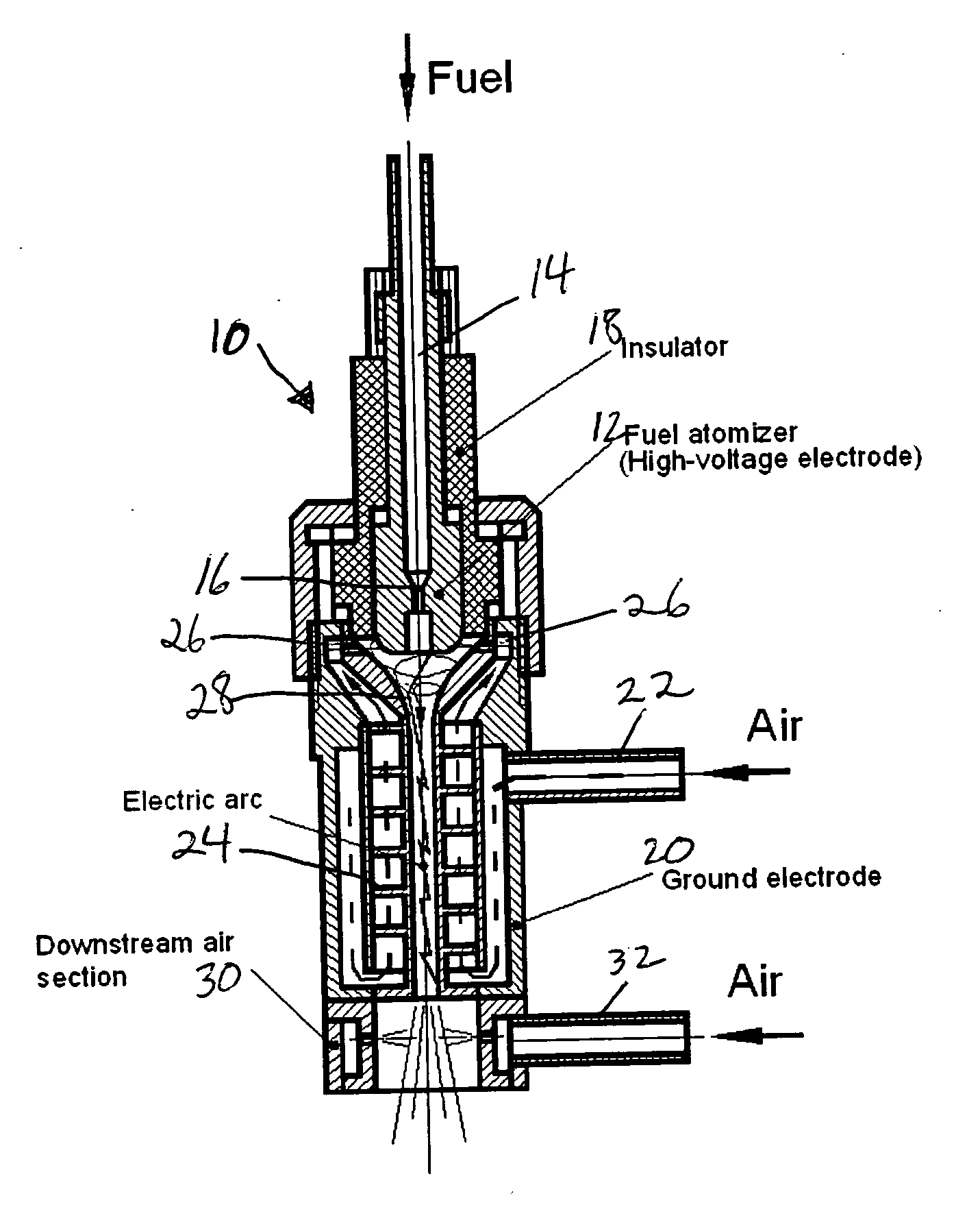
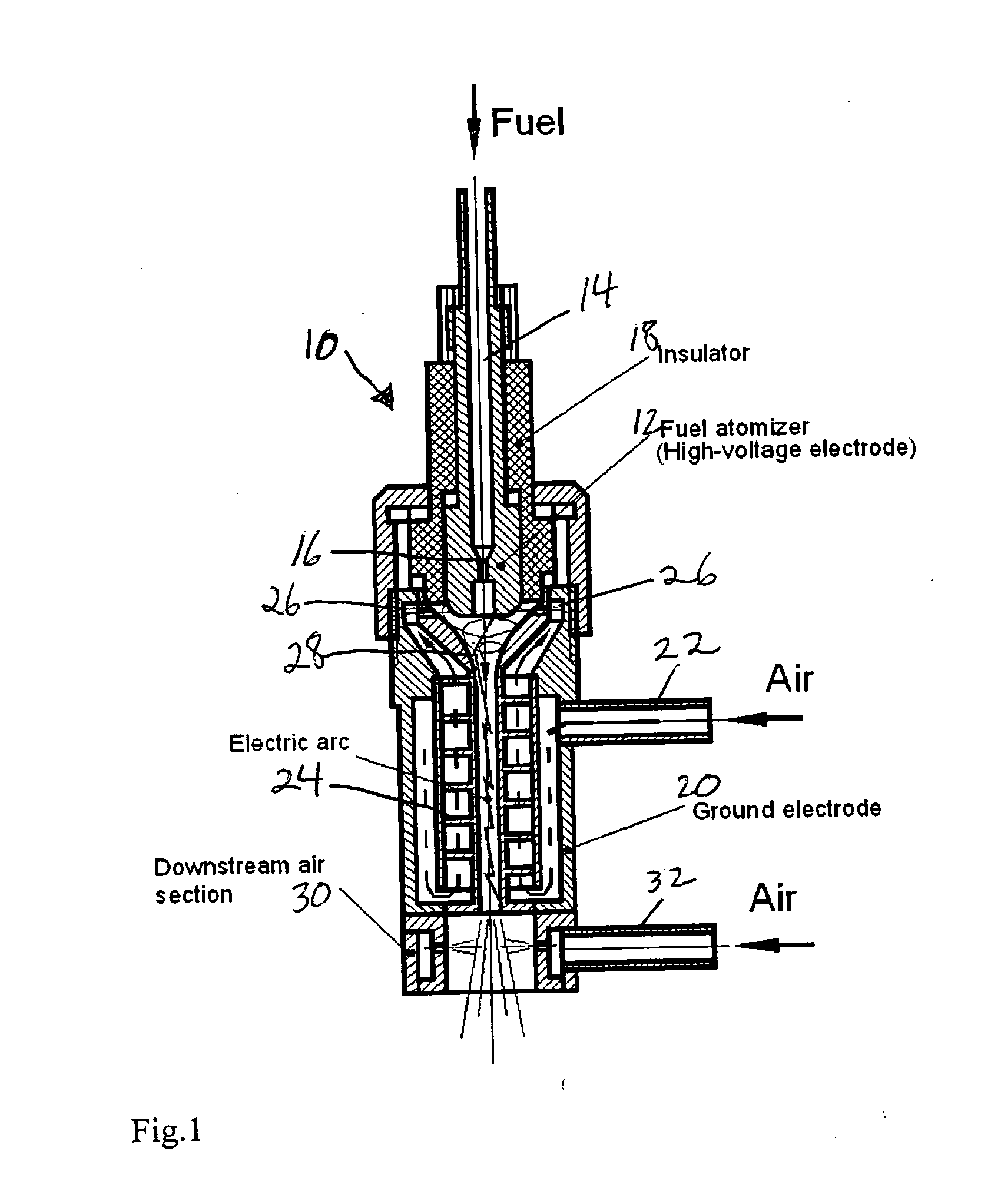
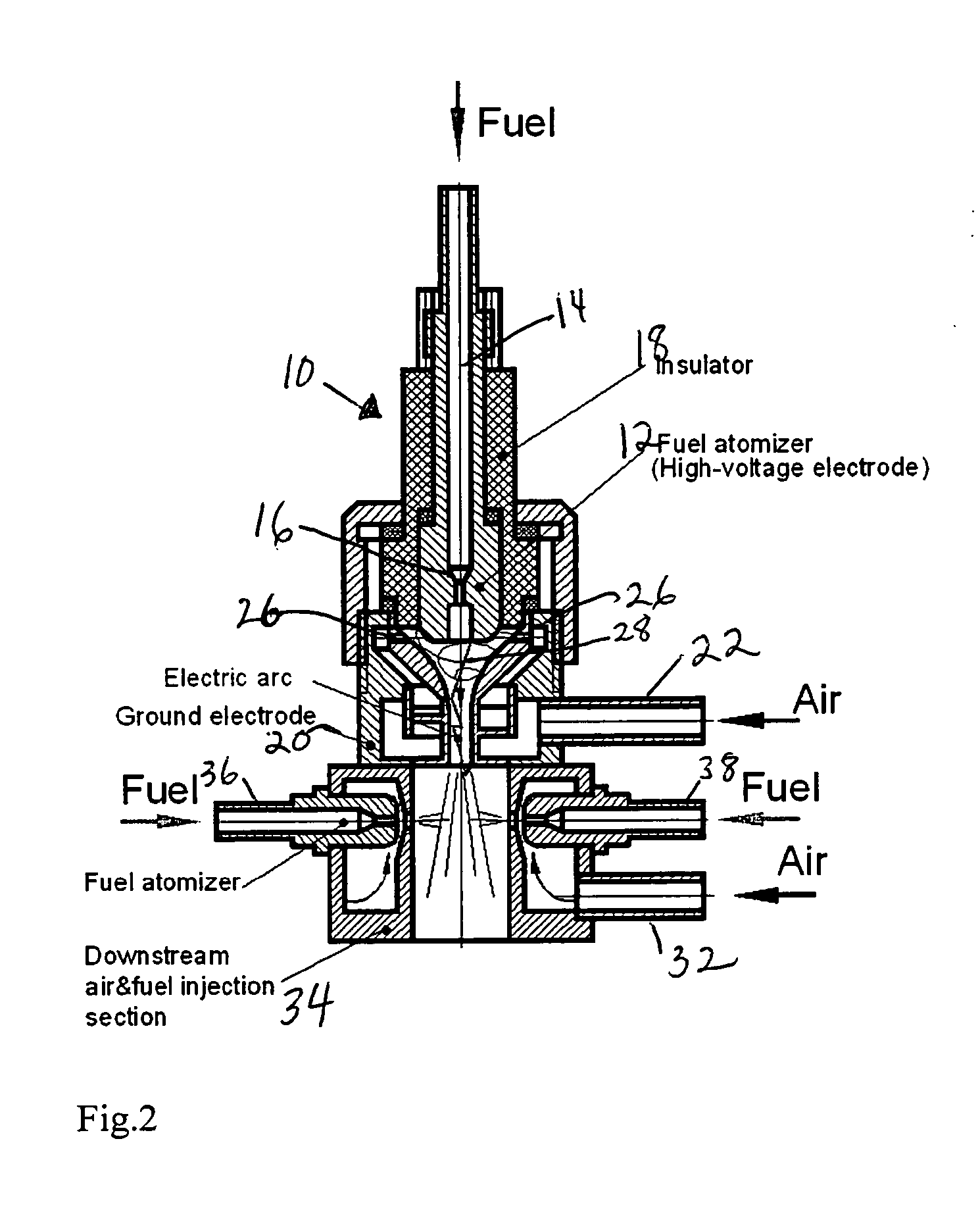
[0018] With reference first to FIG. 1, a high enthalpy, low power plasma reformer 10 includes a high voltage electrode 12 that includes a fuel passageway 14 with an atomizer section 16. The high voltage electrode 12 is surrounded by an insulator 18 that electrically insulates the high voltage electrode 12 from a ground electrode 20. The ground electrode 20 is an annular structure and includes an air inlet 22 and a helical or other similarly suitable structure 24 that directs air upwardly and through gaps 26 to mix with fuel in an arc discharge region 28. This embodiment also includes a downstream air section 30 including an additional air inlet 32.

[0019] In operation, plasma air, at a flow rate in the range of approximately 8-15 liters per minute, is injected into the ground electrode 20 through the air manifold 22 and is caused to revolve upwardly inside the ground electrode 20 by the helical structure 24 to provide efficient air cooling of ground electrode 20's inner surface (the...


PUM

PropertyMeasurementUnit
Temperatureaaaaaaaaaa
Pressureaaaaaaaaaa
Poweraaaaaaaaaa

Abstract

High enthalpy low power plasma reformer. An annular ground electrode includes a air intake manifold and helical structure for directing an air helically along the ground electrode in a heat transfer relation. A high voltage electrode is spaced from the ground electrode to create a gap through which preheated air flows, the high voltage electrode including a passage for delivery of hydrocarbon fuel to an atomizer. A plasma discharge occurs within an electric arc discharge region within the annular ground electrode in which the fuel is partially pyrolized to produce hydrogen rich gas.

Description

BACKGROUND OF THE INVENTION [0001] This invention relates to plasma fuel reformers (plasmatrons) and more particularly to such plasmatrons that operate with high enthalpy and low power. [0002] Plasma reformers, often referred to as plasmatrons, are well-known devices for reforming hydrocarbons to generate a hydrogen rich gas that includes hydrogen, carbon monoxide and light hydrocarbons through the use of a plasma discharge. Plasmatrons are known that use low current and high voltage discharges to provide significant advantages as described in U.S. Pat. No. 6,881,386 and published U.S. patent application 2005 / 0210877, of which some of the inventors of the present application are co-inventors. The contents of these patent documents are incorporated by reference herein. [0003] It is often desired to operate plasmatrons in an “incomplete pyrolysis” mode, that is, at an oxygen / carbon ratio less than one. Known plasmatrons do not operate effectively in this mode because of the low temper...

Claims


Application Information

Patent Timeline
IPC IPC(8): B23K9/00B01J19/08
CPCB01J6/008B01J19/088B01J19/26B01J2219/0871B01J2219/0884B01J2219/0894H05H1/42C01B3/342C01B2203/0255C01B2203/0272C01B2203/0861H05H1/34C01B3/24Y02P20/129
Inventor RABINOVICH, ALEXANDERSAMOKHIN, ANDREIALEXEEV, NIKOLAIPESCHKOFF, ALEXANDER
Owner NANOENERGY GROUP UK
Learn More