Charged particle beam apparatus
a particle beam and apparatus technology, applied in the direction of vacuum obtaining/maintenance, positive displacement liquid engine, therapy, etc., can solve the problems of electric discharge, rare gases and fluorocarbons are hardly removed, and electrochemically stable gases such as rare gases and fluorocarbons are difficult to remove. achieve the effect of high vacuum
- Summary
- Abstract
- Description
- Claims
- Application Information
AI Technical Summary
Benefits of technology
Problems solved by technology
Method used
Image
Examples
first embodiment
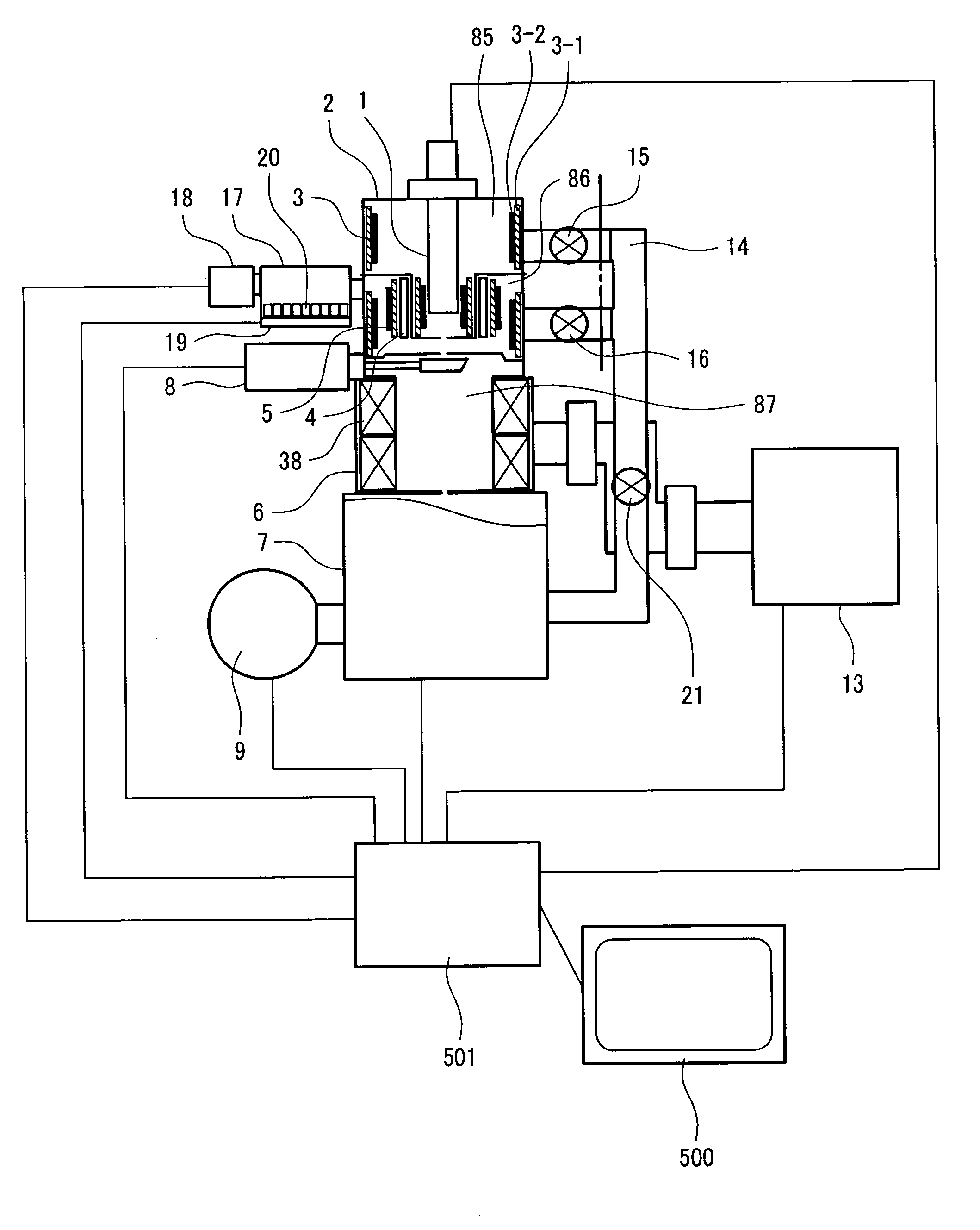
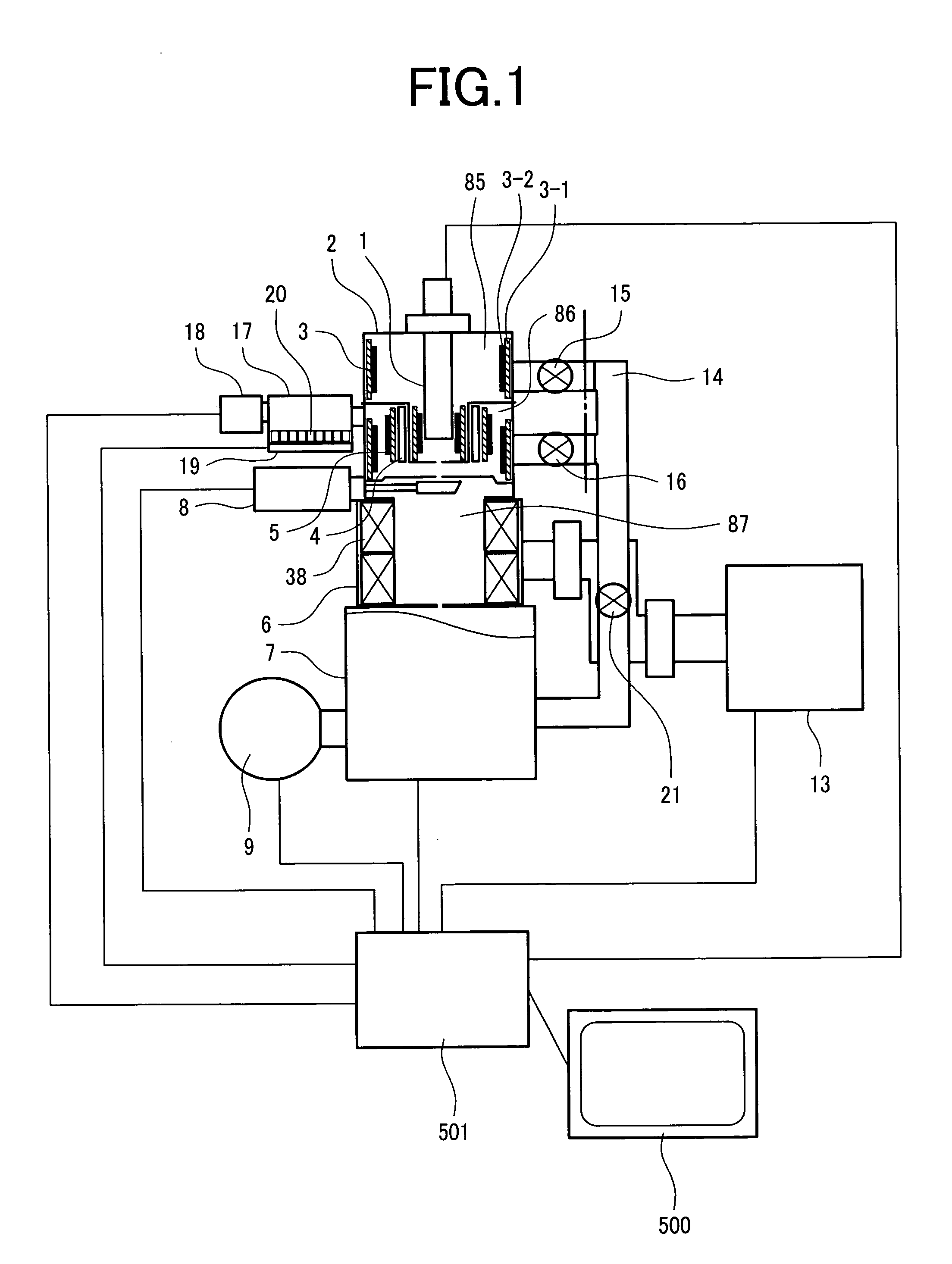
[0050]FIG. 1 shows the structure of a charged particle beam apparatus according to the first embodiment of the invention. This embodiment employs a thermal field emitter electron gun (TFE) as an electron source. This electron source 1 is fitted to a flange with a diameter of 152 mm and connected with a feedthrough to electrodes (suppressor, extractor, tip) (not shown). The electron source 1 is inserted and fixed in an electron gun column 2. The electron gun column 2 consists of a first vacuum chamber 85 and a second vacuum chamber 86 with an opening between them. This leads to a differential pumping effect of a non-evaporable getter pump which increases the achieved degree of vacuum of the first vacuum chamber 85 (decreases the pressure).
[0051] Another possible design for more compactness is that the first vacuum chamber 85 and the second vacuum chamber 86 are integrated into one vacuum chamber to omit part of the pipe including a valve 16 in a rough pumping port 14. The rough pump...
second embodiment
[0077] While the first embodiment concerns an apparatus which uses an auxiliary pump, the second embodiment concerns an apparatus in which a column does not requires any type of auxiliary pump such as an ion pump or turbo-molecular pump.
[0078] Referring to FIG. 7, the basic structure of the apparatus is almost the same as the first embodiment except the following points. First, in the second embodiment, the ion pump 13 for the electro-optics column 6 is eliminated and instead a valve 300 is connected with the sample chamber 7.
[0079] Carbon contaminants on parts with low heat resistance which cannot withstand the baking temperature of 200° C. or so are cleaned in advance. It is particularly important to remove all oily residues on machined surfaces of metallic parts. This reduces generation of hydrocarbon gases which a non-evaporable getter pump hardly removes.
[0080] Although generation of hydrocarbon gases is reduced, all such gases are not removed. Therefore, the second differen...
third embodiment
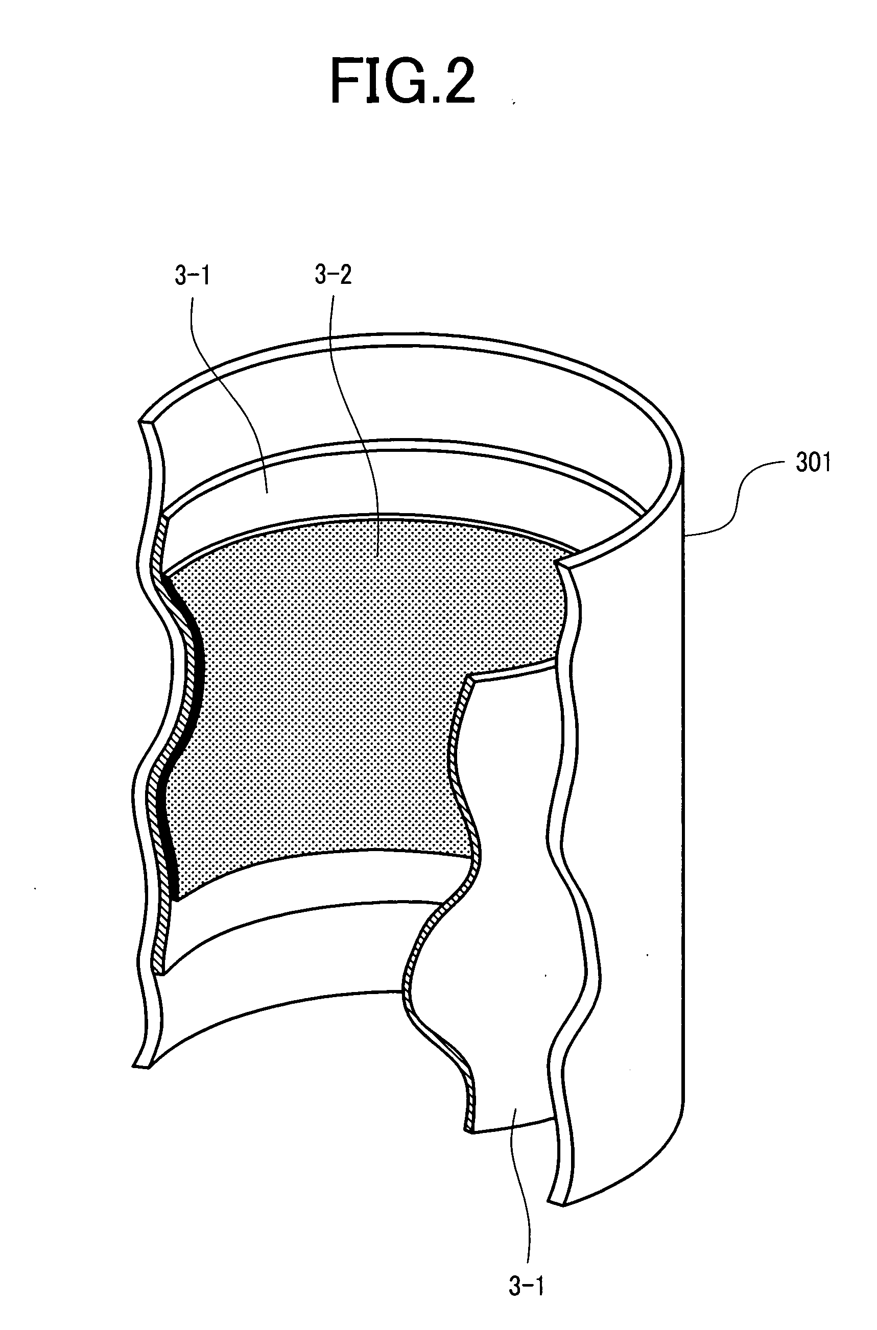
[0083] This embodiment concerns non-evaporable getter alloy in a form other than a sheet or pellet. Specifically, the getter alloy size should be on the millimeter order (less than 10 mm) and typically, grained non-evaporable getter alloy of approx. 3 mm square is easy to handle. The alloy is a bulk alloy of the above size and generates no foreign particles upon contact. However, since the effective surface area of the bulk alloy is smaller, the pumping speed tends to be lower.
[0084] By contrast, the pellet type is porous because it is made by sintering fine particles of several microns to several hundreds of microns and therefore in case of the pellet type, the surface area is larger but fine particles easily come off upon contact.
[0085] In order to increase the surface area of grained non-evaporable getter alloy, its surface should have a convexo-concave shape. The surface of the grained non-evaporable getter alloy used in this embodiment has a convexo-concave pattern which is r...
PUM
 Abstract
Description
Claims
Application Information
 - R&D
- Intellectual Property
- Life Sciences
- Materials
- Tech Scout
- Unparalleled Data Quality
- Higher Quality Content
- 60% Fewer Hallucinations
Browse by: Latest US Patents, China's latest patents, Technical Efficacy Thesaurus, Application Domain, Technology Topic, Popular Technical Reports.
© 2025 PatSnap. All rights reserved.Legal|Privacy policy|Modern Slavery Act Transparency Statement|Sitemap|About US| Contact US: help@patsnap.com


