Dry vacuum pump system for gas sorption analyzer

Inactive Publication Date: 2001-07-10
QUANTACHROME
View PDF4 Cites 33 Cited by
  • Summary
  • Abstract
  • Description
  • Claims
  • Application Information

AI Technical Summary

Benefits of technology

The present invention eliminates the need for a foreline trap and also eliminates the need for using a cold trap in an effort to trap oil contaminants as had been previously used and discussed above.
In a conventional vacuum volumetric analyzer for measuring surface area and pore sizes, the sample analysis requires, at certain stages, an extremely high vacuum for use with the gas sorption analyzer. The input or vacuum side of the turbomolecular drag pump is connected via a manifold (through a valve) to a sample chamber where high vacuum is required. The exhaust or high pressure side of the turbomolecular drag pump is connected by a conduit to the inlet side or vacuum side of the diaphragm pump. The outlet side of the diaphragm pump may be connected directly to atmospheric pressure. The diaphragm pump is turned on to create an environment so that when the turbomolecular drag pump is activated, the exhaust area or high pressure side of the molecular drag side can operate in an environment in conjunction with the diaphragm pump to be most efficient for creating high vacuum in the inlet side of the turbomolecular drag pump. It has been determined that the diaphragm pump provides sufficient vacuum that allows the turbomolecular drag pump to operate at high efficiency and create the high vacuum required. Note that there is no oil roughing pump and that therefore, there is no oil contamination possible to the sample because the pumps, the turbomolecular drag pump and the diaphragm pump, use essentially no oil as a lubricant. The foreline trap is also eliminated.
It is an object of this invention to provide an improved vacuum system for gas sorption analyses systems that require a high vacuum source (10.sup.-5 or less TORR) without contamination to the sample.
But yet still another object of this invention is to provide an improved vacuum system that utilizes the high vacuum turbomolecular drag pump and a diaphragm pump to aid the operation of the turbomolecular drag pump, all of which is essentially oil free for use in gas sorption analysis and vacuum volumetric measurements for determining surface areas and porosities of powdered and porous materials to prevent sample contamination.

Problems solved by technology

One of the problems in using the high vacuum turbomolecular drag pump with the vacuum oil lubricated rotating vane pump as the roughing pump, is that the oil has a vapor pressure at room temperature.
Therefore, it is possible that contaminants of oil vapor could have access to, and in fact, cause the sample that is being analyzed to be contaminated via backstreaming, thus defeating the entire purpose of the system and robbing it of its accuracy.
Furthermore, pump oil may crack and decompose over time, producing additional volatile components.
One of the drawbacks to using this foreline trap is that the trapping material such as carbon has to be reactivated periodically, adding expense and downtime to the system and uncertainty as to when it is time to reactivate the filter material.
Furthermore, the foreline trap limits the ultimate achievable vacuum and impedes the rate at which vacuum is achieved.
This requires replenishing liquid nitrogen, which is costly and undesirable.
If the trap runs out of the liquid nitrogen causing it to warm up, a large amount of oil may be released.
Inasmuch as the turbomolecular drag pump uses such a small trace of lubricant (to prevent bearing wear), the system is essentially dry, the entire vacuum system remains dry, and sample contamination from oil is rendered impossible.
Note that there is no oil roughing pump and that therefore, there is no oil contamination possible to the sample because the pumps, the turbomolecular drag pump and the diaphragm pump, use essentially no oil as a lubricant.

Method used


Image

  • Dry vacuum pump system for gas sorption analyzer
  • Dry vacuum pump system for gas sorption analyzer

Examples


Embodiment Construction

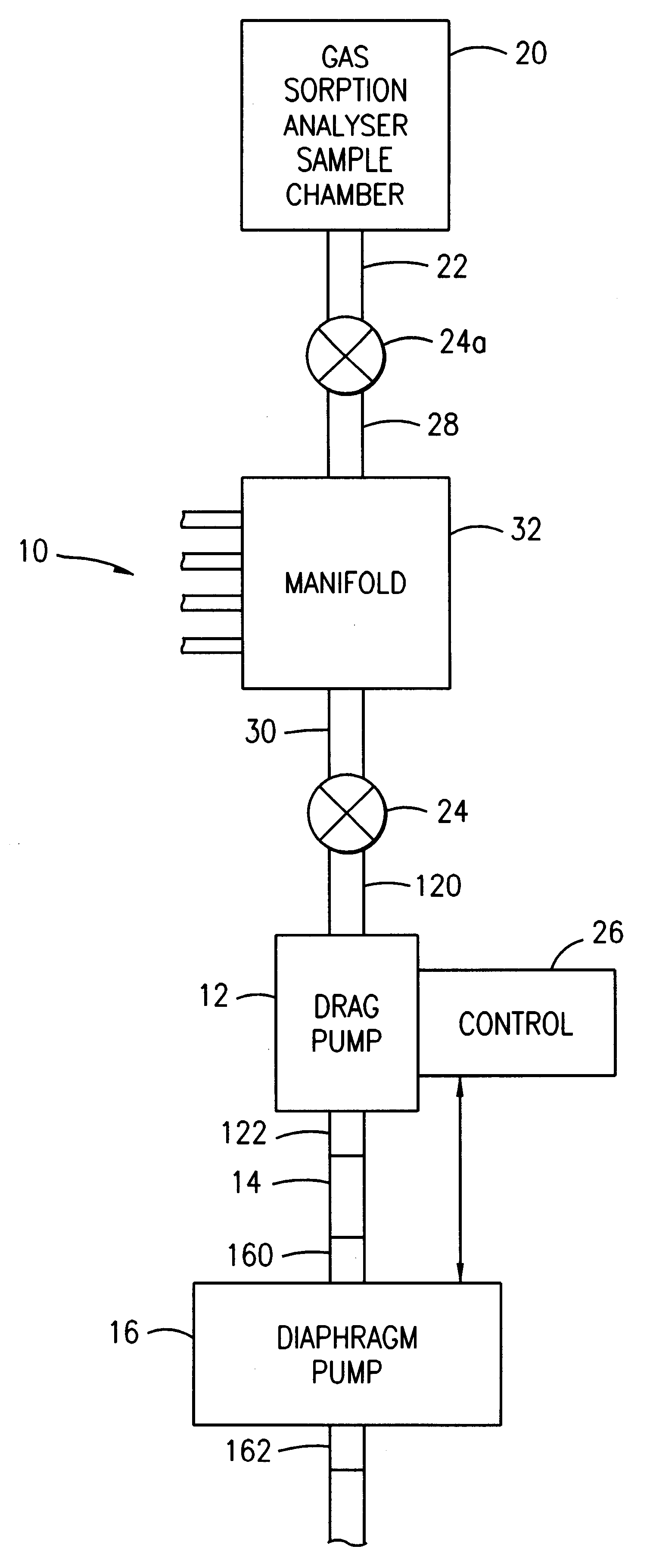
The present invention is shown in the drawing schematically as a vacuum-pumping system 10 that includes a first and second pump wherein the first pump is a turbomolecular drag pump 12 and is connected by conduit 14 to the second pump, a diaphragm pump 16.

The vacuum system 10 comprised of the turbomolecular drag pump 12 and diaphragm pump 16 are ultimately connected to valve 24 through manifold 32 and valve 24a to a gas sorption analyzer sample chamber 20 that is part of the entire gas sorption analyzer system. The overall representation is for illustrative purposes only. Any type of particulate analyzing system that requires a high vacuum in the range down to 10.sup.-5 TORR can employ the present invention. The primary benefit is that the sample, such as the gas sorption sample chamber 20 cannot be contaminated, especially by oil vapor. The analyzer sample chamber 20 is connected by conduit 22 to valve 24a.

The valve 24 is connected to manifold 32 and to the vacuum side or vacuum inl...


PUM


Abstract

A vacuum pump system for creating a high vacuum (below 10-7 TORR) especially useful for vacuum volumetric measurements such as are performed using a gas sorption analyzer on a particulate sample to determine particulate surface area and porosity using a dry, non-lubricant oil-free vacuum pumping system that includes a turbomolecular drag pump having its high vacuum side connected to a vessel that contains the particulate sample to be analyzed, and in series with a dry, oil-free diaphragm pump whose inlet or vacuum side is connected to the high pressure exhaust side of the turbomolecular drag pump thereby eliminating any possibility of oil vapor contamination of the sample since the turbomolecular drag pump and the diaphragm pump use essentially no oil as lubricants.

Description

1. Field of the InventionThis invention relates to a vacuum-forming system for use in gas sorption analyses used to measure surface area and pore analysis of materials, and specifically to an improved high vacuum producing unit that employs a dry vacuum pumping system to prevent pump oil-contamination of the gas sorption system and test sample being analyzed.2. Description of Related ArtThe use of vacuum volumetric sorption apparatus is well known in the prior art for measuring the surface area and the porosity of powdered and porous samples. While the overall systems may vary on certain features, all vacuum volumetric gas sorption systems have certain essential features which include primarily a high vacuum pump, at least one gas supply, sample container, a calibrated volume, and a pressure measuring means.The high vacuum pumping system is critical to achieve sufficiently low pressures for accurate sample measurements. This is particularly important for microporous materials where ...

Claims


Application Information

Patent Timeline
IPC IPC(8): F04B37/00F04B37/14F04B41/06F04B41/00
CPCF04B37/14F04D19/042F04B41/06
Inventor KAEHLER, JOHN W.
Owner QUANTACHROME
Why Eureka
Try Eureka