
Microfiltration devices

a technology of microfiltration and filter, which is applied in the direction of membranes, filtration separation, separation processes, etc., can solve the problems of reducing the filtration performance of microfiltration membrane filters intended for drinking water, the quality control of these types of products sold to consumer markets such as drinking water is usually less stringent, and the performance of microfiltration membrane filters must pass expensive quality control tests, etc., to achieve the effect of improving the filtration performance, improving the performance of the filter, and improving the performan

Active Publication Date: 2007-03-22
STREAMLINE CAPITAL
View PDF12 Cites 44 Cited by
  • Summary
  • Abstract
  • Description
  • Claims
  • Application Information

AI Technical Summary

Benefits of technology

[0012] Another aspect of a method of treating a microfiltration filter having an influent side and an effluent side to improve performance of the filter also is disclosed. This method entails sealing imperfections in surfaces of the filter by flushing the filter with an aqueous suspension of particulates to achieve a coating of particulates of an areal density of about 0.01 mg / cm2 to about 20 mg / cm2 on surfaces of the filter, the suspension having particulates in an amount of about 0.01 gm / l to about 20 gm / l, the particulates having median particle diameter of about 5 μm to about 50 μm and a particle size range of about 0.1 μm to about 200 μm, where flushing of the filter is performed at a flow rate of about 0.02 ml / min / cm2 to about 2 ml / min / cm2.
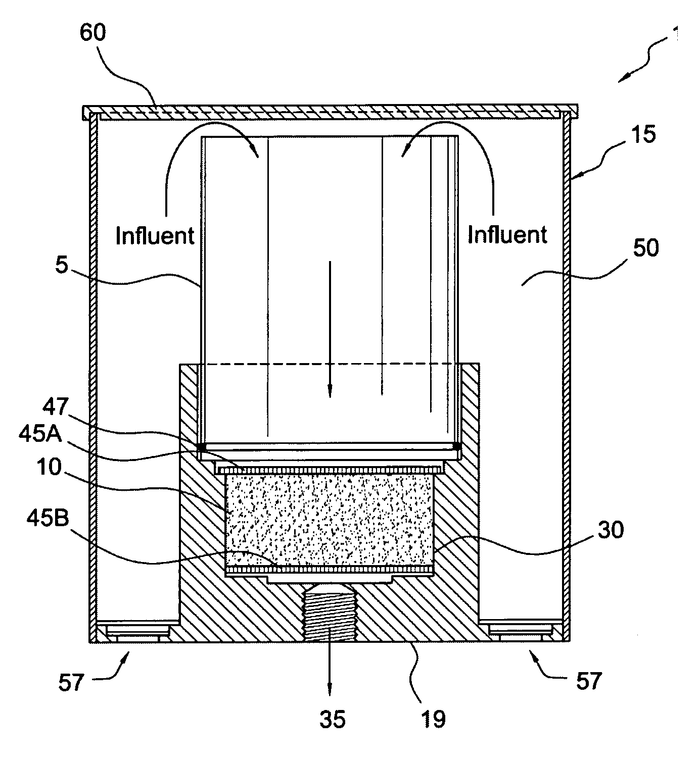
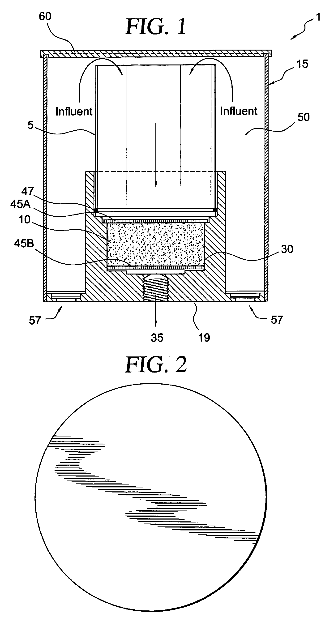
[0014] Also disclosed is a method of treating a hollow fiber membrane microfiltration filter having an influent side and an effluent side to improve performance of the filter. The method entails placing the filter in a filter housing for retaining the filter, the filter housing having an amount of particulates for sealing imperfections in surfaces of the filter, flushing water through the particulates to achieve a coating of particulates on surfaces of the filter, the particulates having median particle size range of about 0.1 μm to about 200 μm, preferably about 0.1 μm to about 100 μm. Flushing of the water is performed at a flow rate of about 0.3 gal / min to about 2 gal / min. The amount of particulates is sufficient to achieve a coating of particulates of an areal density of about 0.01 mg / cm2 to about 20 mg / cm2. Particulates which may be employed include but are not limited to surface activated titanium dioxide, diatomaceous earth, pumice, perlite, silica, alumina, activated carbon, silver, copper, glass fibers, polyethylene, polypropylene, cellulose, metal oxides, metal hydroxides, polyesters, graphite, polyphosphates, glass and mixtures thereof as well as clays, zeolites, (FeOOH), and mixtures thereof. The filter may be included in a cartridge prior to placing the filter in the housing.
[0015] Further disclosed is a method of treating a hollow fiber membrane microfiltration filter having an influent side and an effluent side to improve performance of the filter. The method entails placing the filter in cartridge, placing an amount of particulates for sealing imperfections in surfaces of the filter in the cartridge to form an assembly, placing the assembly in a filter housing for retaining the assembly, flushing water through the particulates to achieve a coating of particulates on surfaces of the filter, the particulates having a particle size range of about 0.1 μm to about 200 μm, preferably of about 0.1 μm to about 100 μm, more preferably about 0.1 μm to about 50 μm and, flushing of the water is performed at a flow rate of about 0.1 gal / min to about 2 gal / min, preferably at a flow rate of about 0.3 gal / min to about 1.5 gal / min. Useful particulates include diatomaceous earth, pumice, perlite, silica, alumina, activated carbon, silver, copper, glass fibers, polyethylene, polypropylene, cellulose, metal oxides, metal hydroxides, polyesters, graphite, polyphosphates, glass and mixtures thereof, as well as clays, zeolites, (FeOOH), and mixtures thereof.
[0016] Further disclosed is a method treating a hollow fiber membrane microfiltration filter having an influent side and an effluent side to improve performance that entails placing the filter in a filter housing for retaining the filter wherein the filter housing includes an amount of particulates for sealing imperfections in surfaces of the filter. An organic liquid then is flushed through the particulates to achieve a coating of particulates on surfaces of the filter. The particulates have a median particle size range of about 0.1 μm to about 200 μm and flushing of the organic liquid is performed at a flow rate of about 0.3 gal / min to about 2 gal / min. The organic liquid may be any of methanol, ethanol, propanol, butanol and mixtures thereof.

Problems solved by technology

In order to achieve these levels of filtration performance, microfiltration membrane filters such as those for use in pharmaceutical applications must pass costly, rigid quality control tests.
However, quality control of these types of products which are sold to consumer markets such as for use with drinking water are usually less stringent then those for pharmaceutical applications.
Furthermore, the filtration performance of microfiltration filters intended for use with drinking water may be reduced by plugging caused by small particles and insoluble organic matter in the influent water which plug the filter.
However, these agents may not kill all of the bacteria and none of these agents have been employed to treat the filtered effluent water to kill remaining bacteria in the effluent.
The disadvantage of this known method is high cost and lack of flexibility to adjust the location of the hollow fiber membrane module in the filter casing as well as lack of reliability of the rubber O-ring seal.
Moreover, even though double O-ring designs have been used in filters to reduce the likelihood of failure, the O-ring may be displaced during installation of the membrane module and lead to failure.
These methods, however, have not been applied to produce stacked hollow fiber membrane modules due to flow direction in the hollow fiber membrane modules.

Method used


Image

  • Microfiltration devices
  • Microfiltration devices
  • Microfiltration devices

Examples


examples 1-6

ILLUSTRATE THIS FIRST ASPECT OF THE INVENTION

example b1

[0071] A commercially available HFM module having about 6000 cm2 surface area and the following specifications is employed: diameter of module: 53 mm, length of module: 115 mm, composition of HFM: polypropylene, composition of module shell: ABS resin, pore size of HFM: 0.1 μm, outer diameter of HFM: 440 μm, wall thickness of HFM: 50 μm, bubble point of HFM: 0.20 Mpa; surface treatment of HFM: hydrophilic agent coating; differential pressure of water flow through module: about 2.5 psi at 0.5 GPM at room temperature. The HFM module is placed into a filter housing and subjected to an initial flushing with water at 0.5 GPM for 5 minutes to establish the initial differential pressure between the inlet and outlet of the module.

example 1

[0072] After initial flushing of a commercially available HFM module having the specifications of the module used in Example B1, the HFM module is flushed with 0.5 gal of precoat flush water that has 1.0 gm of Dicalite 215 (“DE 215”) diatomaceous earth. DE 215 diatomaceous earth, available from Grefco, has a median particle size of 10 micron and a particle size range of 0.1 micron to 30 micron. The flush water is pumped at the rate of 0.5 gal / min through the filter housing. After the flush water is pumped through the filter, both influent and effluent tubes of the filter are immersed in a drum filled with 50 gallon of Atlanta city water. The effluent from the filter is continuously circulated back to the 50-gallon drum. The differential pressure between the influent and effluent sides of the filter is measured with a differential pressure gauge. The results are shown in Table 1.


PUM

PropertyMeasurementUnit
Lengthaaaaaaaaaa
Lengthaaaaaaaaaa
Lengthaaaaaaaaaa

Abstract

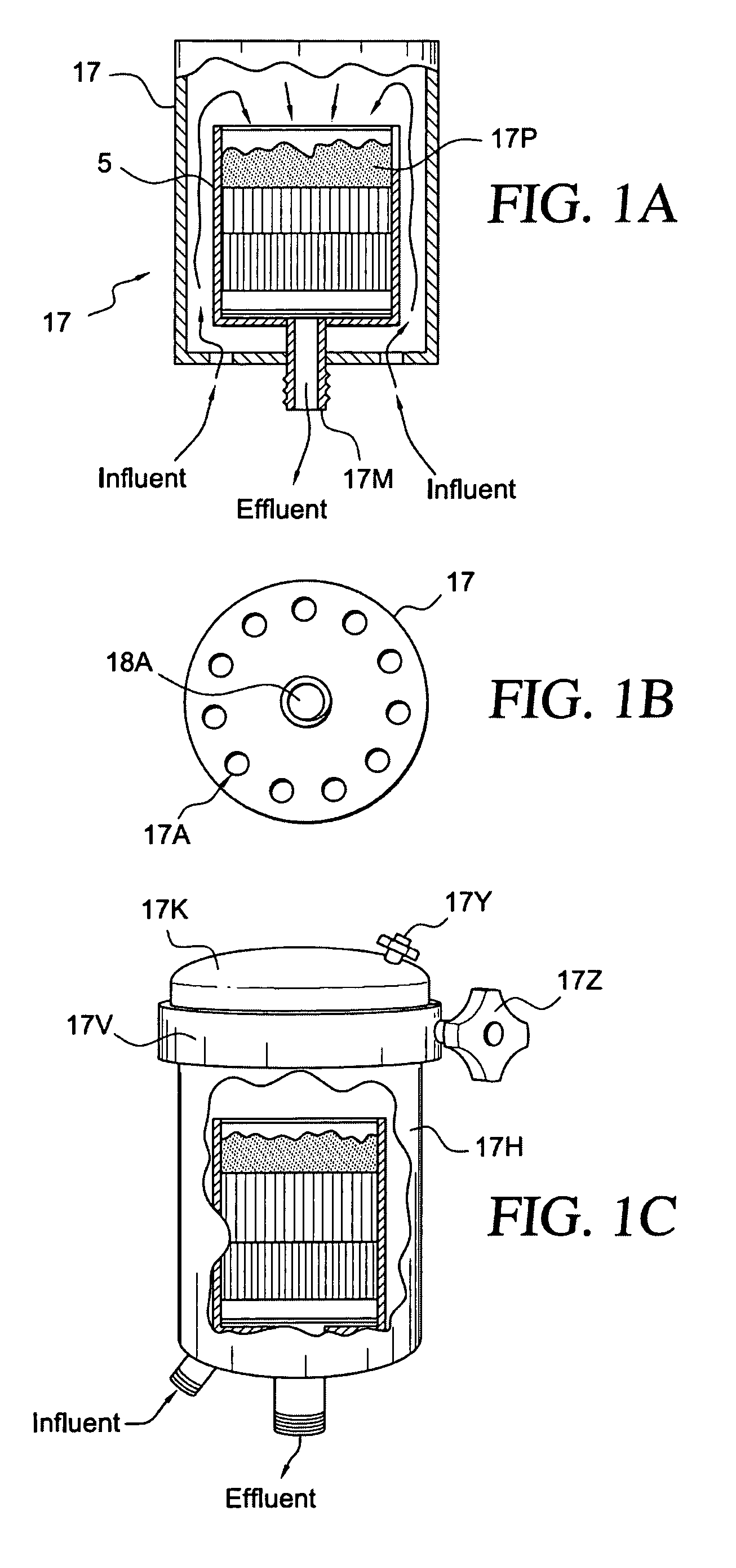
A method of treating a hollow fiber membrane microfiltration filter having an influent side and an effluent side to improve performance of the filter is disclosed. The method entails sealing imperfections in surfaces of the filter by flushing the filter with a liquid aqueous suspension of particulates. Filter cartridge devices also are disclosed. The devices may include a bactericidal chamber. A radial flow filter may be included in the devices. The filter cartridges may include a drain tube positioned within the filter for removing of effluent generated by the filter. A plurality of filter cartridges may be positioned on the drain tube.

Description

[0001] This application claims priority to provisional patent application 60 / 708,700 filed Aug. 15, 2005, and to provisional patent application 60 / 717379 filed Sep. 15, 2005 and to provisional patent application 60 / 727470 filed Oct. 17, 2005.FIELD OF THE INVENTION [0002] The invention relates to microfiltration filters, devices which employ those filters, and to methods for improving their performance. BACKGROUND OF THE INVENTION [0003] Microfiltration membranes are well known for use in removing particulates as small as 0.1 μm diameter and microorganisms as small as about 0.2 μm diameter from fluids such as water and air. These microporous membranes are made of organic polymers or sintered inorganic materials. In order to achieve these levels of filtration performance, microfiltration membrane filters such as those for use in pharmaceutical applications must pass costly, rigid quality control tests. Failed products must be discarded or downgraded for use in less demanding applicati...

Claims


Application Information

Patent Timeline
IPC IPC(8): B01D65/02
CPCB01D61/142B01D61/147B01D63/02B01D63/14B01D2323/286B01D2313/02B01D2313/04B01D2313/44B01D2319/025B01D65/108B01D2313/041B01D2313/042
Inventor CHEN, WEI-CHIH W.NICOLAZZO, KEVIN P.KEPNER, BRYAN E.
Owner STREAMLINE CAPITAL
Learn More