
System and method for augmenting power output from a gas turbine engine

a gas turbine and power output technology, applied in the direction of machines/engines, mechanical equipment, liquid cleaning, etc., can solve the problems of large air consumption of gas turbines, significant cooling of air, and the need for good control of engine air flow, so as to reduce the cost of operation, simplify the hardware, and reduce the effect of gas turbine consumption

Active Publication Date: 2007-03-15
GTE TURBINE EFFICIENCY SWEDEN AB
View PDF11 Cites 138 Cited by
  • Summary
  • Abstract
  • Description
  • Claims
  • Application Information

AI Technical Summary

Benefits of technology

[0020] Evaporative cooling, compressor intercooling, combustor flame cooling or engine wash are established technologies servicing gas turbines all over the world. However, this invention discloses a how these technologies can be combined on the same gas turbine and result in synergetic effects previously not known. Further, the invention discloses how common hardware is used and thereby reducing the cost for practising the invention. The common hardware has its base in the use of water at high pressure as operating media where the advantageous operational effects are found from combining the wash technology with at least one of evaporative cooling, compressor inter cooling or combustor flame cooling technologies. The system is thereby a multipurpose unit for providing multiple functions for enhancing gas turbine performance. The advantageous effects will further be described in the preferred embodiments of this invention. For reference to known technologies, the following patents are cited: U.S. Pat. No. 6,718,771 to Kopko include an evaporative cooling system enabling gas turbine operations at high temperatures. U.S. Pat. No. 5,868,860 to Asplund discloses the use of high liquid pressure for washing of gas turbine compressors. U.S. Pat. No. 6,644,935 to Ingistov describes a nozzle assembly for interstage compressor water injection. U.S. Pat. No. 3,976,661 to Cheng describes power augmentation effects by injecting water into the combustor.
[0021] According to the invention as further described in the preferred embodiments, the invention, i.e. the evaporative cooling method, the compressor intercooling method, the combustor flame cooling method and the engine wash method, can be practised from only one pump if the pump skid is appropriately engineered for that service. It is the purpose of this invention to provide a system for practising evaporative cooling, compressor intercooling, combustor flame cooling and engine washing from only one pump.
[0022] According to the invention as further described in the preferred embodiments requires water to be available at high pressure and at a considerable variation in flow rate. As described above, state of the art pump technology is practising a system with multiple parallel pumps, typically 5 pumps, each one with different flow capacities. By running one, two or more pumps in different combinations a very large range of pump capacities is accomplished. This invention discloses the use of one variable speed pump where the speed is governed by frequency and where the appropriate frequency is set by a frequency controller. It is the purpose of this invention to simplify the hardware by use of only a single pump for practicing evaporative cooling, compressor intercooling, combustor flame cooling and engine wash.
[0023] It is found from experience that practising evaporative cooling, compressor intercooling, combustor flame cooling or engine wash seldom is done according to a fixed schedule. For example; as the air temperature change by the hour, so will the feasibility for evaporative cooling also change. Another example; as the season changes air pollen pollution may result in different fouling characteristics and thereby a different need for washing. These two cases and many more cases require a continuous overview of the engine operating status. Ad hoc decisions are required for an optimized operational result. According to the invention evaporative cooling, compressor intercooling, combustor flame cooling and engine wash when conducted by the same pump skid will simplify the operations as further described in the preferred embodiment of this invention. It is the purpose of this invention to simplify operations.
[0024] According to the invention evaporative cooling, compressor intercooling, combustor flame cooling or engine wash is conducted by the same pump skid which simplifies the operations as well as make more use of the hardware investment. It is clear that if a wash unit is procured from one supplier and an evaporative cooling unit from another supplier, it result in a high investment cost for the two units. Further, it requires significant operator constraints to run several stand-alone units from an operational, spare parts and service requirement point of view. According to the invention one pump unit is used for evaporative cooling, compressor intercooling, combustor flame cooling or engine wash which reduces the capital investment, spare parts and service requirements. It is the purpose of this invention to reduce the capital investment, spare parts and service requirement.

Problems solved by technology

Gas turbines consume large quantities of air.
For a dry and hot desert climate this may result in very significant cooling of the air.
However, this method requires good control of air psychometrics and engine air flow.
If too much water is pumped the air may not be able to pick it up as humidity and all droplets will not evaporate.
The excess water will wet the duct walls where it may cause corrosion and a flooding problem.
A drawback with the scrubber and the sprayer method as described above is that the cooling effect is limited by how much water the air can pick up before reaching saturation.
However, a draw back with this method is the high costs for the unit investment which has shown to limit the applicability of this method.
Too much water will result in “overspray” as the air can not pick up the excess water.
The excess water may harm operations as it may result in corrosion damage and flooding of the air duct.
The contrary situation with too little water will not saturate the air and full cooling effect will not be accomplished.
Cooling of the compressor results in less compression work which, in turn, results in more surplus power available on the shaft.
Another issue of concern is the build up of fouling in the compressor.
Air breathing machines like gas turbines consume large quantities of air.
Compressor fouling results in a change in the properties of the boundary layer air stream of the gas path components.
The deposits result in an increase of the component surface roughness.
As air flows over the component the increase of surface roughness results in a thickening of the boundary layer air stream.
The thickening of the boundary layer air stream has negative effects on the compressor aerodynamics.
Further, the thick boundary layer and the strong wake turbulence result in a reduced compression pressure gain which in turn results in the engine operating at a reduced pressure ratio.
Anyone skilled in the art of thermodynamic working cycles understands that a reduced pressure ratio result in a lower efficiency of the engine.
Further, fouling of the compressor reduces the compressor isentropic and polytropic efficiency.
Reduced compressor efficiency means that the compressor requires more power for compressing the same amount of air.
Due to high rotor speeds and short retention time for the liquid, the wash efficacy is not as good compared to the crank wash.
However, even though, as indicated above, there exist a large number of different techniques for augmenting the power output of gas turbine engines, such as a stationary gas turbine engine, there is no known technique that is able to provide an increased power output over a wide range of operating conditions as the same time as it offers a cost efficient and user-friendly solution.

Method used


Image

  • System and method for augmenting power output from a gas turbine engine
  • System and method for augmenting power output from a gas turbine engine
  • System and method for augmenting power output from a gas turbine engine

Examples


example 1

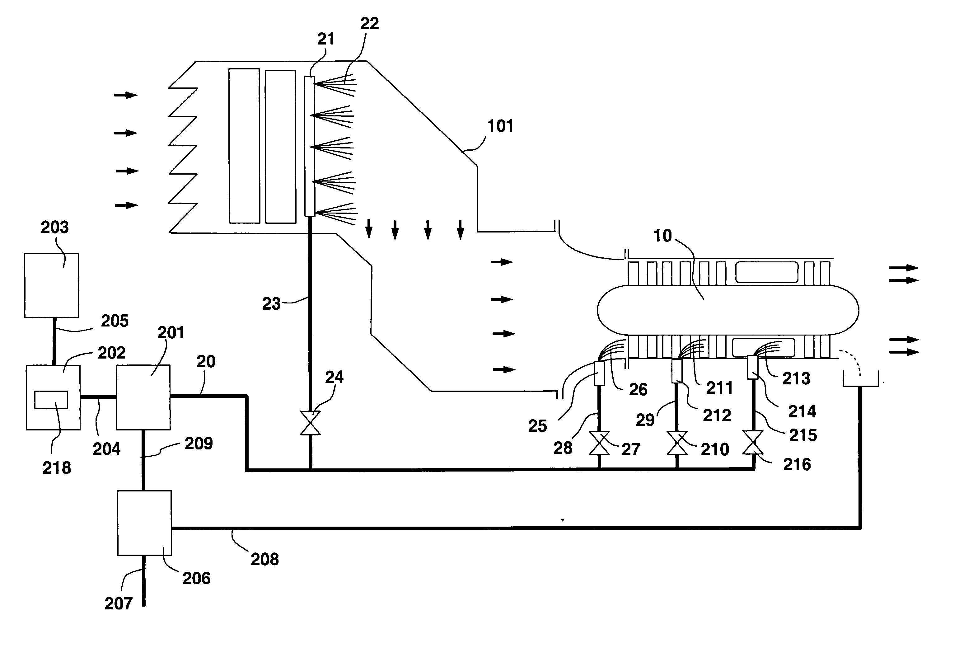
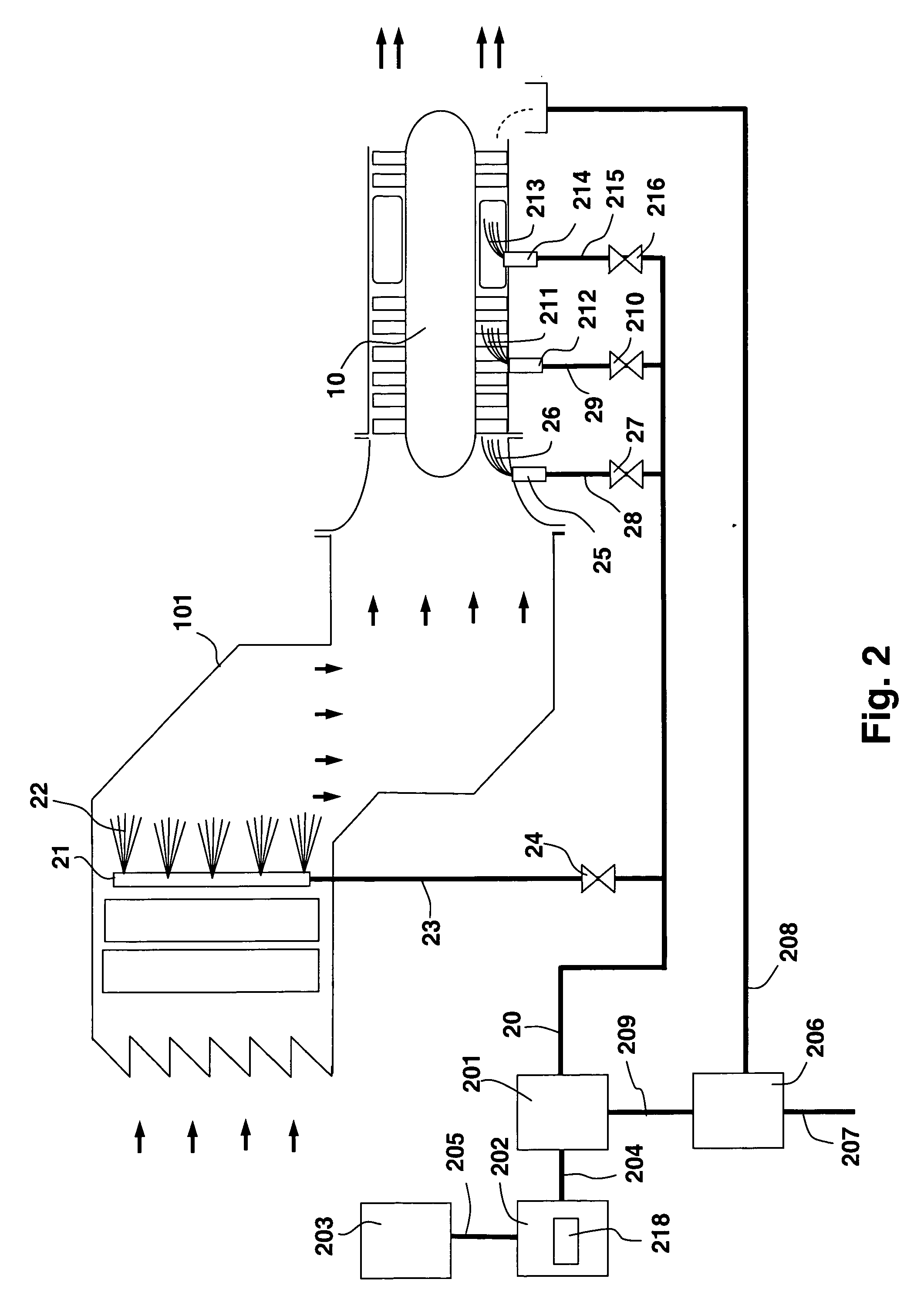
[0059] In this example the operator runs his gas turbine plant as a “power peaker”, i.e. the plant is in operation only limited hours a day for the purpose of supplying extra power when the grid demands it. The operator activates the evaporative cooling as to augment the power output. This is done by starting pump unit 201 and opening valve 24. The other valves on pipe header 20, i.e. valve 27, 210 and 216, are closed. In this mode of operation the evaporative spray cooling is running resulting in a fog upstream of the compressor. The fog will efficiently cool the air as the droplets evaporate. However, fogging has the disadvantage of coalescing airborne foreign particles which will appear as a wet and sticky fouling of the compressor. Now, it is a desire to wash that fouling away before shutting down so that the next run can start with a clean compressor. The operator accomplishes this by conducting a three minute on-line wash before shutting down. At three minutes before shutdown ...

example 2

[0060] This operator runs a gas turbine in power production and has both evaporative cooler and compressor intercooler installed. He has activated the evaporative cooling unit as to augment his power output. During the night the temperature drops. He is seeing that the air relative humidity is increasing as of the colder temperature. Eventually the dew point temperature will be reached in the morning where water no longer can evaporate. This disables him to use the evaporative cooler. To maintain his power augmentation capability he decides to switch to compressor intercooling. This is done by closing valve 24 and simultaneously open valve 210. When the sun rises in the morning and the temperature rises the relative humidity is lowered. He now decides to switches back to evaporative cooling by closing vale 210 and simultaneously open valve 23.


PUM


Abstract

The present invention discloses a method and system for augmenting shaft output of stationary gas turbines that can be used in multiple modes of operation. The system comprises a washing unit (25, 27, 28) adapted to inject a spray (26) of atomized liquid so as to impinge on the compressor blades (12) in order to wet said blades (12), thereby obtaining a release of fouling material from said blades (12); and at least one liquid injection unit (21, 23, 24, 29, 210, 212, 214, 215, 216) adapted to inject a spray (22, 211, 213) of atomized liquid into an air stream of said turbine duct (101) or at the gas turbine (10) in order to increase a mass flow of said air flow, wherein the power output from said gas turbine engine can be augmented. With the invention follows also benefits such as fuel savings and improved environmental performance by reduction of emissions.

Description

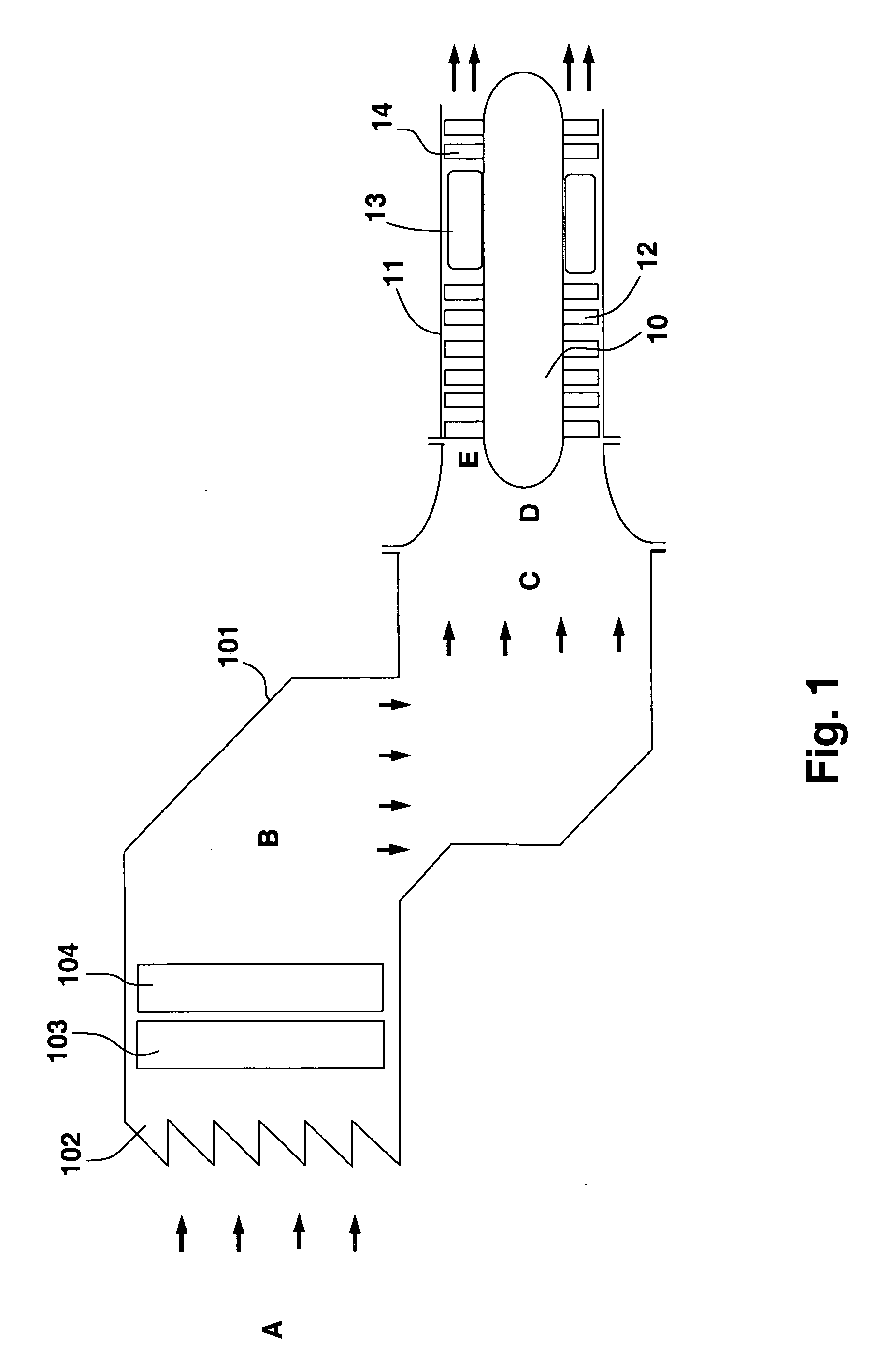
FIELD OF THE INVENTION [0001] This invention generally relates to the field of stationary gas turbines. A gas turbine engine comprises of a rotor inside a casing. The rotor comprises of a compressor for compressing ambient air and a turbine for expanding the exhaust gases. The compressed air is delivered to a combustor burning fuel together with the compressed air resulting in combustion gases expanding through the turbine. The turbine drives the compressor. As the turbine power output is greater than the compressor power requirement, surplus power is available on the shaft. The surplus power is used for driving loads such as a generator, a pump, a compressor, a propeller or alike. The present invention particularly relates to a method and system for augmenting shaft output of stationary gas turbines that can be used in multiple modes of operation. With the invention follow benefits such as fuel savings and improved environmental performance by reduction of emissions. BACKGROUND OF ...

Claims


Application Information

Patent Timeline
IPC IPC(8): F01D1/00
CPCB08B3/02B08B9/00F02C7/1435F02C3/305F01D25/002
Inventor HJERPE, CARL-JOHAN
Owner GTE TURBINE EFFICIENCY SWEDEN AB
Learn More