
Nonaqueous secondary battery

a secondary battery and non-aqueous technology, applied in the direction of cell components, final product manufacturing, sustainable manufacturing/processing, etc., can solve the problems of short circuit, shorten the life of the battery, and flow of heat generation, so as to achieve poor coatability and lower electronic conductivity

Active Publication Date: 2007-03-01
SANYO ELECTRIC CO LTD
View PDF8 Cites 78 Cited by
  • Summary
  • Abstract
  • Description
  • Claims
  • Application Information

AI Technical Summary

Benefits of technology

[0050] With the invention as in claims 9 and 10, a nonaqueous secondary battery can be obtained that exerts the effects of the invention as in claim 1, both in the case of a nonaqueous secondary battery having a rolled electrode array (claim 9) and in that of nonaqueous secondary battery having a stacked electrode array (claim 10). Particularly if the structure in claim 9 is employed, it will be possible to obtain a current pathway from most portions of the collector edge surfaces, so that the structure will be favorable for a high-output battery. Since this structure entails metal being exposed over a long extent in the roll direction and a high probability of short circuits occurring due to burr or the like, its possession of the protective layer of the present invention will be particularly effective.
[0051] With the invention as in claims 11 and 12, the fact that powder of an inorganic material such as electronically conductive carbon, semiconductor material or electrically conductive oxide is dispersed in the insulative high-molecular substance means that it is a simple matter to form a protective layer that has lower electronic conductivity than the metal composing the collector, and that moreover is made of non-insulative material. Particularly if at least one item selected from a group consisting of polyimide, polyamideimide and polyvinylidene fluoride is used as the insulative high-molecular substance, it will be possible to form with especial efficacy a protective layer made of non-insulative material.
[0052] With the invention as in claims 13 and 14, because the protective layer uses an insulative high-molecular substance, a carbon material that imparts conductivity to the insulative high-molecular substance, and a filler material, differences in color arise among the protective layer, the active material compound layer and the collector after drying, so that via optical sensors it is possible to detect clearly the boundaries between the active material compound layer and the collector, and between the protective layer and the active material compound, which means that during manufacture of the nonaqueous secondary battery it will be possible, using optical sensors and an image processing system, to detect stacking deviations or rolling deviations in the electrode plate arrays automatically, and thereby the manufacturing efficiency of nonaqueous secondary batteries will be enhanced. If at least one item selected from a group consisting of polyimide powder and alumina powder is used as the filler material, the protective layer can be colored particularly effectively, and hence it will be possible to detect even more clearly the boundaries between the active material compound layer and the collector, and between the protective layer and the active material compound.
[0053] With the invention as in claim 15, the fact that the specific surface area of the carbon material is no more than 40 m2 / g means that the boundary between the protective layer and the active material compound can be detected reliably via optical sensors. This is because in cases where the carbon material's specific surface area exceeds 40 m2 / g, the protective layer and the active material compound are both the same black color, which makes detecting the boundary between the two problematic for optical sensors. Also, a lower limit of 1.5 m2 / g will preferably be set for the carbon material's specific surface area, since if it is below 1.5 m2 / g, the carbon material's particle size will be so large that coatability with the protective layer will be poor.

Problems solved by technology

With such a structure, in which a exposed part of the collector, composed of metal foil, of each electrode of one polarity faces an electrode of the other through an interposed separator, a large current that could cause heat generation will flow should powder that separates from the electrode or a part thereof due to dropping or vibration, etc., of the device penetrate through the separator and cause a short circuit.
If this happens, the short circuit will result in the battery generating abnormal heat when used, which will lead to a fall in capacity and also shorten the battery's life.
More specifically, during manufacturing of the electrode roll, which is formed by laying the positive electrodes and negative electrodes over one other with separators interposed therebetween, the negative electrodes are positioned, specific insulating tape of a thickness greater than the height of any burr that is generated on the positive and / or negative electrodes during formation of the electrode roll and could cause a short circuit with the positive electrode is stuck to at least one face of the positioned negative electrodes at the position where short-circuiting with a positive electrode is anticipated.
However, since the use of the insulating layers as short-circuit prevention layers makes charging / discharging possible—as long as no short circuit occurs—even with the separator in a pierced state such as described above, there is the problem that if the battery continues to be used in such a state over a prolonged period, the damaged portion will develop into rupturing of the separator, which will cause a large short circuit that will result in the battery generating abnormal heat.
To detect stacking deviations or rolling deviations in such electrode array automatically, use has long been made of radiolucent imaging, but even so, detection of such deviations is problematic because of the small amount of X-rays that penetrate.
Furthermore, detection of stacking deviations or rolling deviations in an electrode array in which a protective layer is formed as described above would be even more of a problem in terms of identification, as it would be necessary to detect each of the boundaries among three items: the active material compound layer, the protective layer and the collector.

Method used


Image

  • Nonaqueous secondary battery
  • Nonaqueous secondary battery
  • Nonaqueous secondary battery

Examples


first embodiment

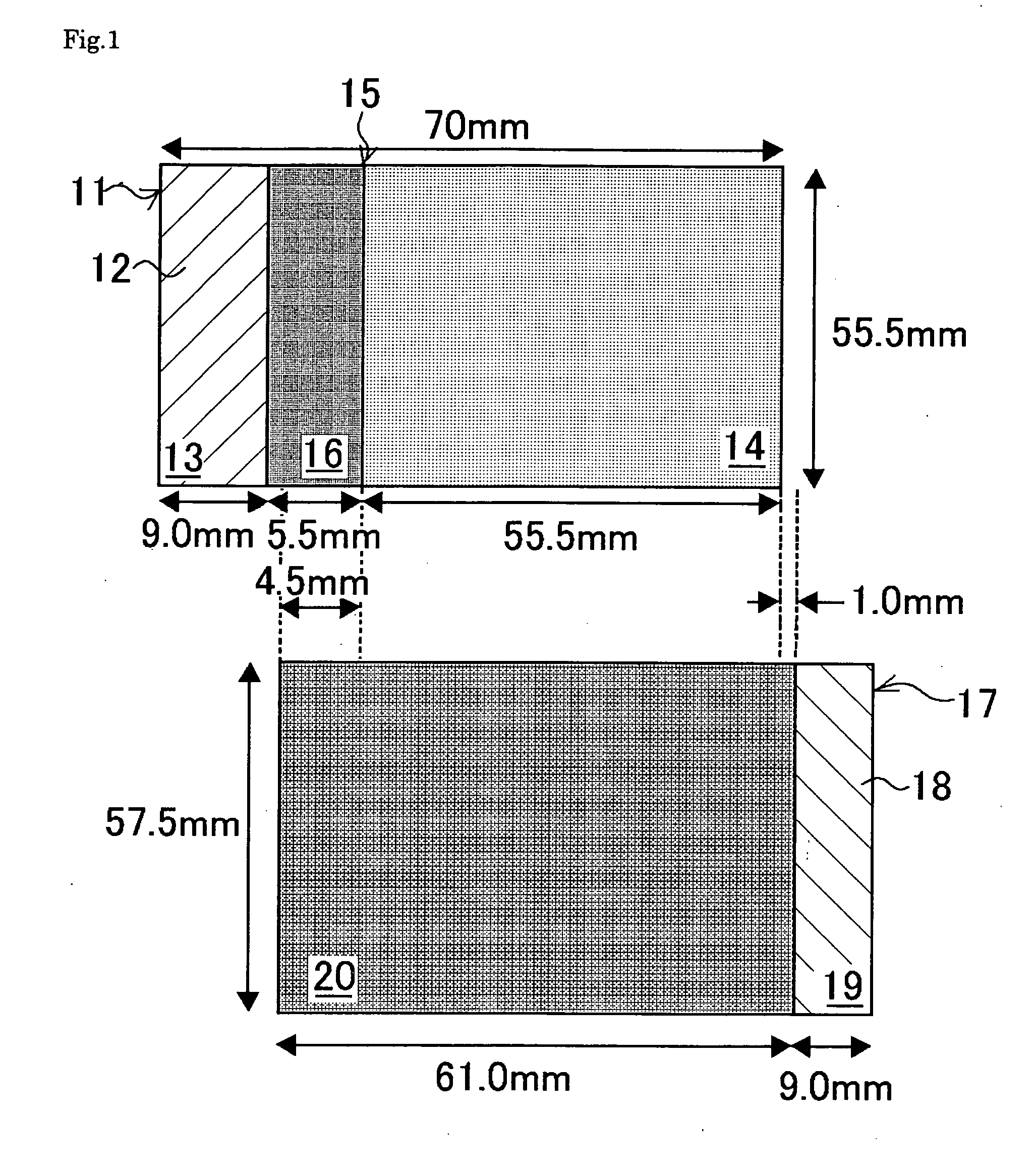
[0068] First will be described, with reference to FIGS. 1 to 3, the method of fabricating a nonaqueous secondary battery that was used in the first embodiment. FIG. 1 is a plan view illustrating the electrode dimensions in the nonaqueous secondary battery of the first embodiment, FIG. 2 is a top view seen through the outer case, illustrating in outline the structure of the nonaqueous secondary battery of the first embodiment, and FIG. 3 is a cross-sectional view along III-III in FIG. 2.

(Fabrication of Positive Electrode)

[0069] The positive electrode 11 was fabricated as follows. First, an active material compound slurry was prepared by mixing 94% by mass of positive electrode active material composed of compound oxides of lithium, nickel, cobalt and manganese with 3% by mass of powdered acetylene black, graphite or other carbon and 3% by mass of a bonding agent constituted of polyvinylidene fluoride (PVdF), then adding N-methylpyrrolidone (NMP) to the resulting mixture and kneadi...

second embodiment

[0084] An active material compound slurry was prepared by mixing 94% by mass of positive electrode active material composed of compound oxides of lithium, nickel, cobalt and manganese with 3% by mass of powdered acetylene black, graphite or other carbon and 3% by mass of a bonding agent constituted of PVdF, then adding NMP to the resulting mixture and kneading it. This active material compound slurry was then applied evenly to one face of the positive electrode collector 12 made of 20 μm thick aluminum foil so as to leave, at the edges of the electrode, a portion 13 where the aluminum foil was exposed, thus forming a positive electrode plate coated with an active material layer 14. Following that, the positive electrode plate coated with the active material layer 14 was passed through a drying machine, where the organic solvent that had been needed for preparation of the slurry was removed and the plate was dried. Afterward, the dried positive electrode plate was rolled with a rolle...

third embodiment

[0086] In the third embodiment, a protective layer was fabricated using the same procedure as in the second embodiment except for the preparation of the protective material, which was prepared as follows. In an NMP solvent, 1 g of polyimide powder and 0.1 g of carbon powder with specific surface area 40 m2 / g were mixed into 20 g of binder solution containing 5% by mass of PVdF, and further NMP was added so that the whole mixture amounted to 25.1 g. As with the second embodiment above, the results of the experiments using optical sensors are compiled alongside those of other embodiments in Table 3.


PUM


Abstract

A nonaqueous secondary battery 10 of the invention has an active material compound layer 14 deposed over at least one face of a collector 12 made of metal foil and is equipped with a positive electrode 11 having a portion 13 in a part of which metal is exposed. The positive electrode 11 together with the exposed-metal portion 13 faces a negative electrode 17 through an interposed separator 23, and on that part of the exposed-metal portion 13 that faces the negative electrode 17 through the interposed separator 23 there is formed a protective layer 16 made of a material whose electronic conductivity is lower than that of the metal and which moreover is non-insulative. With such nonaqueous secondary battery 10, should part of an electrode pierce the separator and contact with the other electrode, the battery will be gently discharged, thereby averting abnormal heat generation by the battery and additionally enabling the battery's abnormality to be sensed by the equipment via the fall in battery voltage. Thus, there is provided a nonaqueous secondary battery of excellent safety that can prevent abnormal heat generation due to a short circuit caused by burr, powder or the like piercing the separator.

Description

1. FIELD OF THE INVENTION [0001] The present invention relates to a nonaqueous secondary battery. More particularly it relates to a nonaqueous secondary battery of excellent safety in which abnormal heat generation due to short circuits occurring when burr, powder or the like pierces the separator can be prevented. 2. RELATED ART [0002] With the rapid spread of mobile electronic equipment, electric vehicles (EVs), hybrid electric vehicles (HEVs) and the like, the specifications required the batteries used in such items have become more stringent with every year. In particular, such batteries are required to be compact and lightweight and to have high capacity and output, as well as to excel in cycling characteristics and give stable performance. Accordingly nonaqueous secondary batteries, which have high energy density compared to other batteries and of which are typified by the lithium ion battery, are receiving much attention in the field of secondary batteries. The lithium nonaqu...

Claims


Application Information

Patent Timeline
IPC IPC(8): H01M4/66H01M2/34H01M4/02H01M4/13H01M4/131H01M4/133H01M10/05H01M10/052H01M10/058H01M10/0585H01M10/0587
CPCH01M4/0404H01M4/131H01M4/133H01M4/66H01M4/661Y02E60/122H01M4/667H01M4/669H01M6/10H01M10/05H01M4/662Y02E60/10Y02P70/50H01M4/13
Inventor YANAGIDA, TOSHIOOKUMURA, YOSHINOBUYAMAUCHI, YASUHIRONAKANISHI, NAOYANOHMA, TOSHIYUKI
Owner SANYO ELECTRIC CO LTD
Learn More